Safety valve for the water heater: why you need it, how to put it. Non-return valve: installation features.
A non-return valve is a type of shut-off valve of direct action. It is designed to ensure the flow of water in the right direction and to prevent the flow direction from changing to the opposite direction. Protects against high pressure pipelines, pumps and other equipment, and in case of damage to individual sections it limits the amount of liquid leaking out of the system. Used in modern systems heating and water supply.
Classification
By constructive features these devices are divided into:
- Disk spring.In this version of the valve, the locking mechanism is a disc with a rod on the spring. In the presence of normal pressure, the disk is in the open position and allows a flow of water. When the pressure falls and the liquid tends in the opposite direction, it presses the disc against the seat, blocking the hole.
- Ball spring.The mechanism consists of a metal ball and a spring. In the absence of liquid pressure, the ball is pressed against the walls of the hole, overlapping it. Such a device is intended for pipes with a small diameter.
- Lifting-rotary.The basis of the design is a lid fixed to the axis. With normal water movement, the lid is in the open position, with the return current - it slams.
- Lifting spools.The principle of operation is that the spring-loaded spool is pressed against the water flowing back and closes the hole.
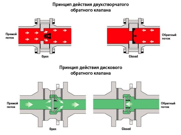
- Bivalve. Used for large diameter pipes. Protect large systems from water hammers, soften their effect.
The basic metals from which the locking mechanisms are made are brass, cast iron, stainless steel. Experts consider brass structures to be the most suitable for household use.
Where is it installed, before or after the counter?
Since the purpose of installing the shut-off element is flow control in one direction, an arrow indicating the direction of water movement is necessarily shown on its surface.
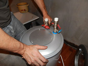
It is advisable to install the non-return valve in the pipe section after the water meters, on the pipe through which cold water enters the boiler.
In heating systems, the valve allows you to divide the contours, direct the water flow in the desired direction in each of them and prevent the already warmed liquid from getting back into the cold water supply system.
The presence of this simple and inexpensive device helps prevent serious and costly breakdowns.
Order and nuances of installation
Before installing the shut-off element after the pump, note that the power of the device will be reduced by overcoming the resistance of the spring or the shutter. But the pump does not have to constantly pressurize the system, it is created once and subsequently only supported. Thus, the operation of the unit becomes more rational.
On the water supply system check valve connect before pumping station, using a shotgun in case of its replacement, or to the suction pipe behind the ratchet.
If the device is installed on an already installed water supply system, the installation site is selected between the pump and the pumping station. It is necessary to make a rupture of the pipeline, to install one valve at one end of the pipeline and connect it with the other end. 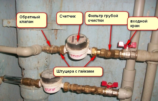
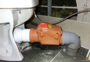
AT sewer pipes The device is installed to prevent reverse flow of waste water and waste of life. In this way, it is possible to avoid leakage of liquid through the toilet while blocking the common sewerage. The unit is installed horizontally or vertically in an active or new sewage system, in places where there are pipes of the required diameter. The diameter of the check valve here can be from 50 to 100 mm. The connection is made using an adapter from pig iron to plastic. For tapping into a cast iron pipe, you need an angle grinder.
On a single-circuit heating system, a check valve is needed only if the flow of water in it is provided by movement due to heating, without the participation of a pump.
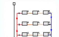
There are systems of parallel movement, where along with the natural flow of water a pump is used. The installation of the valve in this case is necessary.
To install the shut-off element on the water supply and heating system, tools for tapping into the pipe are required: a bulgarian for metal pipes, and a regular hacksaw for a plastic one. On the pipes of metal for the connection it is necessary to make a thread with the help of a thread-cutting tool. A non-return valve is installed using a swivel and gas wrench. After that, the pipe, to which the device is screwed, is connected to the other part with a suitable key. For connection plastic pipes special adapters are used.
If you are a little knowledgeable in plumbing and have free time, to install the unit yourself will not be difficult. Non-specialists in this matter can always delegate the work to an experienced master.
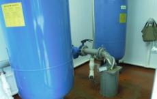
One of the most important elements of the system of autonomous water supply is a check valve for water. It performs the function of protecting against such interruptions in the operation of the water supply, such as lowering the water pressure, switching off the pump or leaking.
The check valve has a simple design in the form of a brass cylinder with a spring built into it and a round overlapping plate. The valve is only able to flow water in one direction.
Where to install the check valve: in the well or in front of the pumping station?
The installation of a non-return valve is possible either at the inlet of the suction pipe itself, or immediately before.
Installation of a check valve at the entrance to the pump station
A non-return valve connected to the system does not allow water to flow from the suction pipe back into the well or into the well after the pump is disconnected. This very useful function of the non-return valve is indispensable for organizing flows in heating and water supply: for all subsequent pump starts, there is no need to re-fill the entire system with water. And this not only facilitates the work of the pump itself, but also provides an almost instantaneous supply of water to the consumer. The choice of the valve should be based on the diameter of the pipe, in the section of which the installation of a non-return valve is planned. Keep in mind that the non-return valve creates additional resistance to the water flow in the system, so that the pump pressure can drop by 0.5 atm.
How to install a check valve for water correctly?
The design of the non-return valves used in household plumbing with the spring-loaded membranes installed in them makes it seemingly possible to install the valve with any orientation in space. After all, the check valve in any case, regardless of whether it is horizontally mounted, vertically or otherwise, should work normally. In fact, so it is, it is possible that you will never have such a problem. But it will be superfluous and be safe, because what the devil does not joke, as they say ...
The spring installed in the check valve is so weak that it can not withstand various dirt and deposits. But in the course of operation they inevitably form on the walls of the check valve and the membrane! But if the spring of the check valve was more powerful, then the sense of using a check valve would also be lost, because then it would be very difficult to pass water in one direction, and in the other it would not pass at all.
So, if you are not a masochist and do not want the water supply system to bring additional problems and costs in the future, install a check valve for water with an up arrow, i.e. strictly vertical. And the more accurately you do it, the longer the check valve will last without any failures and censures.
It is difficult to find a system of pipelines or water supply, which does not need repair or that would do without installing backflow blockers.
With their help, we manage to perform many useful actions and to limit automation of all processes, without using complex schemes or electronics. Check Valves so and are good, that with apparent simplicity they can perform extremely useful work.
Features and purpose
Before the valve is the task to prevent changes in the flow of fluid in the water pipe. Why and why should it be installed? Its installation allows control heating and free movement of the flow in one direction and overlapping access for the reverse direction of the water supply.
Most of the problems occur when a system directed at a one-way flow suddenly appears a malfunction, and the fluid begins to flow in another direction into the well. Examples of similar situations (when the flow returns to the well) can be a great many.
For example, surface pump set and brought to the well with the help of special hoses. By these hoses pumped water in the water supply system. However, without a filled chamber, the pump can not work. In his chamber, there is a constant presence of a sufficient amount of liquid.
Without the use of backstops in the water supply, the owners would have to run to the pump every time a water supply becomes necessary.
But its installation (repair) on the pump solves many problems. It is mounted at the lowest point of the hose. After pumping, enough liquid will automatically block the remaining water in the hose holding, thus the chamber is full.
Now the pump can work independently, and its owner will be calm and able to do his own business.
The installation of such a device significantly reduces the likelihood of occurrence of freelance and emergency situations on pipelines or devices that serve. These products are widely used both in industry and in domestic heating, water supply or sewage.
They are installed in front of water meters, in domestic pipelines, on heating circuits, in wells, etc. And with the help of such devices it is possible to break the pipeline into several sections, each of which will be isolated in case of an emergency.
Product design and operating principle
There are many types of these products, which differ in the degree of tightness and reliability. Under different environments and operating conditions can be selected suitable device, which will reliably perform its function.
In accordance with the design can be classified as:
- Rotary pattern. As a locking mechanism is a disk. It is fixed to the axis, which is located outside the passage section. The installation of this type is popular with a pipeline diameter of more than 50 mm.
- Bicuspid specimen. On its axis on the center of the flow section there are two leaves. Also more suitable for pipes with a diameter of more than 50 mm. The design is not ideal and creates a significant loss of pressure of the working fluid.
- Disk, in which the locking mechanism serves as a disk. This disk is perpendicular to the axis. Use such products for small pipe diameters.
- Spring It is arranged in such a way that the closing of the shutter occurs as a result of the force of the spring. They can be installed in any position.
- The spring-loaded sample also has a spring in its design. But in this case the shutter closes as a result of gravity. The installation site of this type of product is horizontal or vertical, with the supply of working medium from the bottom up, the pipeline.
The principle of operation in the system is the shut-off of the flow section by the gate in the event that the working medium changes the direction vector.
When there is no flow, in the inlet branch pipe of the working flow is equal to the pressure value in the outlet branch pipe.
The bolt comes into motion, which closes the passage section and closes. In this case, the force vector, which holds the shutter in the closed state, is directed to the opposite side of the movement of the working fluid.
In the inlet pipe with increasing pressure, the force vector of the flow will be opposite to the force vector, which keeps the bolt closed.
When the pressure of the working fluid is significantly higher than the opening pressure, the bolt will begin to shift and open the cross-section of the mechanism. This is due to the difference in pressure.
In the outlet branch pipe, with increasing pressure, the vectors of the working medium and the force that keeps the bolt closed are co-directed. With increasing pressure, the bolt will press harder against the body.
As soon as the pressure from the flow drops, the spring or any other locking element immediately block the pipes, since it will not have more resistance from the flow side.
Return water can not return, because its design does not provide for the opening of the closure element under pressure from the other side. Thus, the carrier remains on the other side, while the new stream at any time can open latch and get into the system.
Installation of the locking mechanism
The installation scheme of the product has both general rules and its features when installed on different systems.
General installation rules:
- It is necessary to take into account the movement of the working medium and to correctly install the device so that the arrow on the body shows in the direction of flow.
- Install the device better, taking into account the possibility of access for replacement (or if repair is needed), which is not worth doing without a master.
- Lifting rotary mechanisms must be installed only horizontally.
- Consider the possibility of disassembling the product for revision.
- Threaded connections must be additionally sealed. To do this, fit-tape, skeins of flax or silicone.
- If you need to work with a dirty environment, it is recommended to mount a filter at the entrance coarse cleaning, as wearing a large particle can damage the operation of the device, as shown in the photo below.
Stages of work
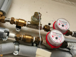
Installation of the non-return valve (and its repair if necessary) on water is conducted on the simplest scheme. AT apartment buildings, where there is a separate supply of water, you should put the appliances after the water meter. If a water heater is used, it is necessary to put the mechanism at the inlet of the pipes, which is engaged in the supply of cold water.
Installation of a non-return valve to the sewer is carried out in the rooms that are on the first or second floor. The location of the installation is determined, depending on the presence of the gangway on the sewer to drain the working medium in the floor.
In this case, the mechanism should be placed at a height of not more than 35 cm from the floor. If the drainage of the gangway does not have, then it is necessary to install it for sewerage in a section located higher than the highest point of entry of water disposal. Mounting is performed on the socket or the free end of the pipe.
Also, the products of the reverse action are mounted on separate risers in the sewage system, however this happens rarely, as it is only possible to block the sewage system as a last resort. It is especially difficult to do this for those who live in an apartment building.
Instead, they are mounted directly in front of each plumbing unit. For example, before the toilet (as pictured below) or a sink.
Its installation on the pump or ventilation is carried out directly in the ventilation duct. Usually, install the product behind the fan in the well for ventilation.
It is very important at installation to remove all gaps between the well and the valve and only then, to install the fan. There are also overhead mechanisms that assume installation in front of the fan. If the valve is mechanical, electricity is also supplied to it, for monitoring purposes.
Its application to the well is mandatory. Here it is required to put it on the pump to prevent leakage from the pipeline when the pump is not running.
Also, they are mounted on the hoses themselves, thus breaking down into several separate parts, each of which will contain water. That practically excludes the possibility of idle operation of pumping equipment or other systems that ensure the operation of the well.
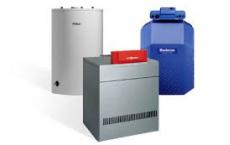
Its installation for heating is considered the most complicated process. In homes where autonomous heating is necessary to put the product on the return line before entering the boiler.
To improve the work of the heating system circulation pump. To protect the pump from a hydraulic shock when switching on and off, it is necessary to set the reverse danfoss valve after the pump.
Check valve for downhole pump is a device that allows you to move the flow of water in only one direction. In this case, from downhole pump to the points of draw-off. In order to understand the necessity of installing a check valve inwater well , we will consider what happens in it when the pump is turned on and off.
1. The pump is on. Water, under the influence of the pressure created by the pump, rises from the well and enters the membrane accumulator and further to the points of draw-off. If water is not consumed, it accumulates in the accumulator before reaching the upper pressure threshold in which the pressure switch turns off the pump. There is no reverse flow of water into the borehole, since the pressure created by the pump interferes with this.
2. The pump is switched off. The pressure that created the pump disappears and now, in principle, nothing prevents water from flowing back into the well under the influence of gravity. So that this does not happen and there is a check valve. Without it, when the downhole pump was switched off, there would be no pressure in the system. And every time you turn on the pump, you have to fill it again and again with water. Even if a check valve is installed at the entrance to the diaphragm accumulator (from the pump side), all the pipes that are before it should be filled with water every time, spending electricity on it.
Where to install a check valve for a downhole pump
Here we are smoothly and approached the question of the location of this node. Clearly, it must stand between the pump and the membrane accumulator, otherwise the installation of the latter loses all meaning. But where is more precise? Most preferable is the location of the valve in the area of the downhole pump on the HDPE pipe. In this case:
1. When the pump is turned off, the minimum amount of water is drained back into the well, that is, a minimum amount of electricity is required to replenish this loss when the inclusion of a downhole pump.
2. Through the downhole pump in the opposite direction will pass a minimum amount of water, reverse side its impeller (extremely undesirable operating mode of the pump).
3. The more empty space that is not filled with water between the diaphragm accumulator and the pump, the more the water will accelerate when the latter is turned on and, consequently, the more the hydro shock will be.
In practice, a check valve for a downhole pump is installed directly at the outlet of the pump itself. If the pump is shallowly loaded into the borehole and the borehole near the house, then one valve can be limited. If the pump is lowered deeply and the artesian well is at a respectful distance from the automation, then at least one more valve should be put at least. Usually it is placed next to the accumulator and automation.
Types of check valves for a pump in a well
Structurally, all check valves for a downhole pump are identical - a stainless steel or brass housing, inside which there is a spring-loaded plate made of plastic or metal with a rubber seal.
In conclusion, it should be noted that many models of downhole pumps have a check valve in their design - Grundfos, Pedrollo, Lowara, etc. But, for example, pumps do not have a built-in check valve.