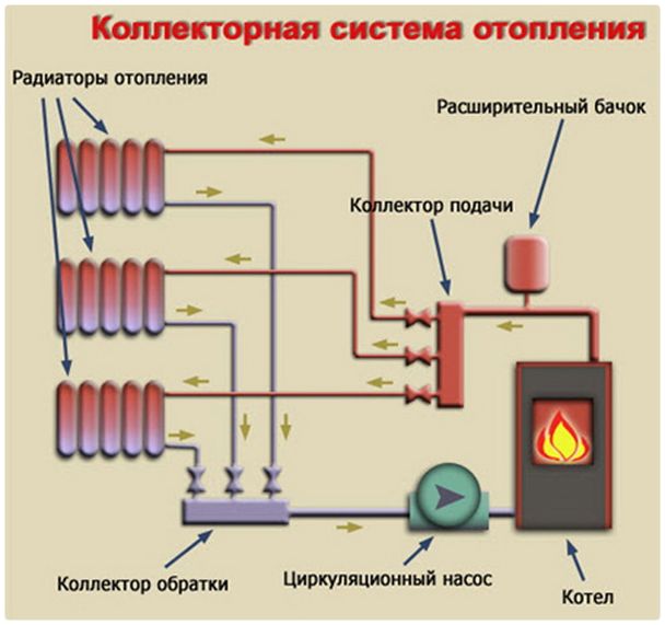
Collector system for heating a multi-storey building. Collector variant of heating
Perhaps, the collector heating system is the most effective way of heating any house, regardless of the number of floors and rooms. Such a scheme is often called radial, as it, unlike other heating systems, has a rather complicated (at first glance) wiring consisting of several separate threads (rays), although it can be mounted independently if one knows the principle of the contour functioning.
What it is, what advantages it offers - we discuss this and other issues in detail and understand this article.
But first, let us clarify the definitions. For the heating of residential buildings, various schemes are used, so it is difficult for a layman in this field to understand the essence of the matter, if to operate only with specials / terms.
What is a collector? This word denotes various technical products. In the case of a heating system, this is a device that regulates the volume of the coolant flowing into this or that thread of the circuit.
The disadvantage of other heating schemes is the uneven heating of radiators along the entire length of the route, unjustified heat losses and a number of others. But the main disadvantage is the lack of the possibility of changing the degree of heating of the batteries (and in some cases, their complete shutdown) without interfering with the operation of the boiler equipment, that is, changing the mode of operation of the battery.
It should be noted immediately that using collectors is not something special. The use of such heat engineering devices can be complex, regardless of which circuit the attached circuit is mounted on.
The device of a collector of heating
It is easy to understand, if you consider the simplest modification of the product.
As can be seen from the figure, only 2 heating circuits can be connected to such a collector.
More complex options. For example, for 3 separate "thread".
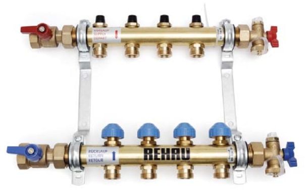
The disadvantage of these valves is the impossibility of regulating the supply of coolant to each circuit. Therefore, for a residential structure in which there are a number of different types of premises in which it is necessary to maintain a different temperature, it is advisable to use more advanced reservoir modifications. The figures show some variants of this engineering solution.
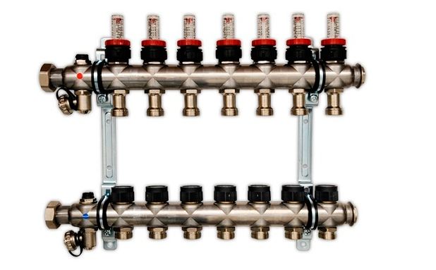
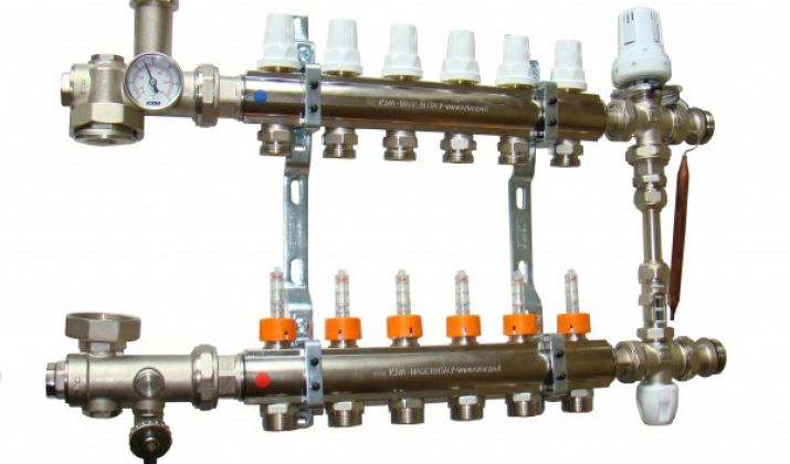
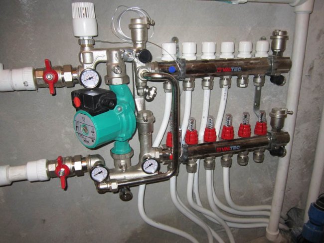
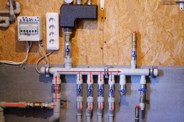
In the photo below - a collector with built-in flowmeters.
Principle of operation of the reservoir
The coolant is supplied to it, which is fed through the pipe system from the boiler. The device has several nozzles, which are the inputs and outputs for the connected circuits. This ensures their independent supply (decoupling) of thermal energy, which allows it to be metered (regulated) by a single thread.
Heating schemes (options)
What type of heating devices to connect, their type and number, the location of the collectors - this is determined even at the design stage of the entire heating system. There is no single recommendation here. With regard to the structure in 2 floors, you can put either 1 "multichannel" collector, or 2 - 3 less functional. The specific scheme is chosen based on the number of rooms and consumers of thermal energy.
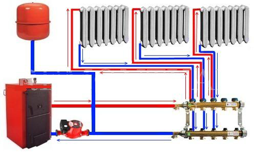
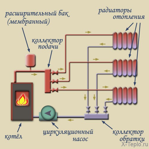
In a simplified form, for greater clarity, it can be presented as follows:
The order of the arrangement and are already separate questions. The collection circuit allows to equip the system of various types and any configuration. For example, with heating of the subsidiary structure (greenhouses), with heated floors.
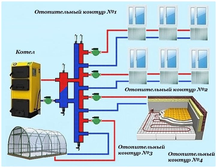
The advantage of the collector systems is the possibility to regulate the degree of heating of each room individually. This allows not only to reduce the overall cost of heating, but also make living in the house more comfortable. For example, to maintain the temperature in living quarters at a level of 24 ° C, and in the utility rooms - somewhat less. As for the rooms on the ground floor, which are used as pantries, it can be reduced to +5 ºС to avoid freezing of the walls.
The disadvantage of the collector heating system is the high cost of installation. After all, if you lay several separate threads, then the consumption of pipes and materials (insulation, sealant, etc.) increases.
The main problem of the heating system of a large house is the rapid cooling of the coolant. This is typical for classical single-tube and two-pipe systems. Their alternative is the properly designed collector system for heating the house with their own hands: circuits, nodes, groups.
Installation of a collector heating system
First, you need to decide - do you need a collector system for water heating? It is used only in those cases where the rate of cooling of the coolant in the pipes under the classical scheme will be critical or in large houses. The main difference is the separation of the system into several heating circuits, working independently of each other.
Despite the positive side, it will be problematic to make proper collector heating by one's own hands. Therefore, before choosing a specific scheme (or its composition), several important factors of the actuality of the installation need to be considered:
- Large area of the house. For a uniform thermal distribution, several heating circuits must be made;
- Inefficient installation of the tee circuit. It can affect the hydraulic distribution throughout the heating system;
- The need to switch off the heating of individual rooms. This is one way to optimize energy costs.
Considering these factors, the collector heating of a two-story house is the most optimal way of organizing autonomous heat supply.
If, in calculating the standard scheme, the difference between the temperatures in the supply and return pipes is more than 25 ° C is the first sign of the need for the installation of a heating system for a private house.
Composition of the collector heating system

At the first stage it is necessary to get acquainted with the principle of design of autonomous heat supply. The simplest scheme of collector heating consists of a single distribution unit, to which separate mains of the system are connected.
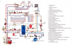
The structure includes standard components - a boiler, a circulating pump, an expansion tank and a safety group. The collector unit is installed directly next to the boiler and consists of two elements:
- Input. It is connected to the supply pipe from the heating device and distributes the hot heat carrier along the contours;
- Output. To it conduct return branch pipes from separate highways. It is necessary to collect the cooled water and its direction to the boiler for further heating.
Complex collector groups for heating are equipped with devices for regulating the volume of the coolant supply - thermal heads (input) and mechanical limiters at the output.
It is best to purchase the collectors of factory production. Since they are designed for certain heating parameters.
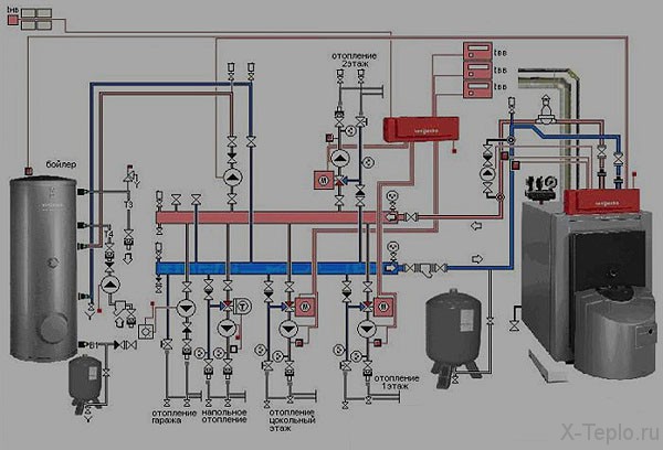
This principle is used to organize the heat supply of a one-story private house, where the capacity of the circulation pump will be sufficient to ensure normal pressure in the pipes. For a two-storey building, two collector groups can be installed for heating. One of them will be intended for distribution on separate contours, and the second serves as the main component of the warm water floor.
For such a scheme it is necessary to calculate the parameters of each circuit. Most often there is a need to install the following additional components:
- Circulating pumps for each circuit;
- Mixing unit. It is necessary to regulate the temperature of the coolant in the reservoir. The channel connects the straight and return pipe and by means of a regulating device (two or three-way valve), flows are mixed with different degrees of heating.
The traditional scheme of the collector heating of a two-story house includes distribution centers on the first and second levels. But it all depends on the total area of the premises and, as a consequence, on the length of individual highways.
Also it is necessary to take into account heat transfer and optimal thermal conditions in each room.
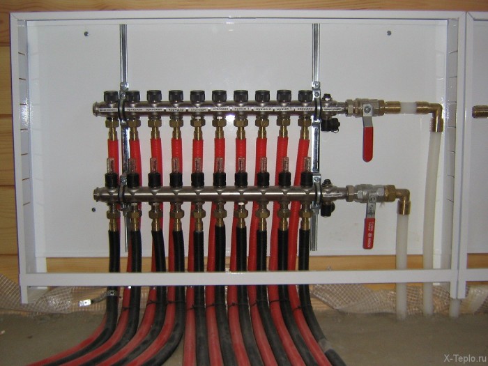
All collectors located in residential premises must be installed in special closed boxes.
Collector heating of the house with own hands
Is it difficult to manufacture and install a heating system of this type with your own hands? It should be remembered that it is much more complicated than single-tube or two-tube. The main difficulty lies in the accurate calculations of each collector node for heating.
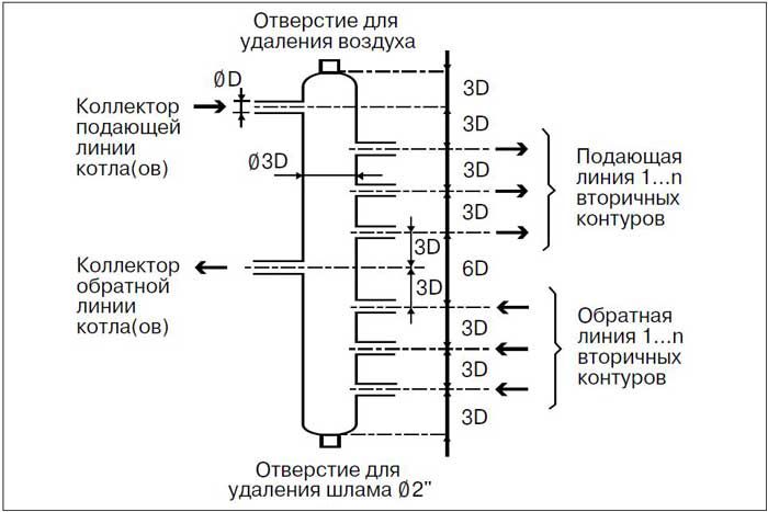
If the heating of the collector type is intended for a house with a large area and a number of separate mains - it is recommended to install a distribution manifold with the function of a hydraulic compensator. Its difference from the standard consists in connecting the supply and return manifold with the help of nozzles. Its installation offers the following advantages:
- Prevents the occurrence of hydraulic shocks;
- Compensates the pressure difference due to the thermal expansion of the coolant in the supply pipe;
- Automatic mixing of water flows and as a consequence - reduction of energy costs.
The comb of this type is mounted in the collector system of water heating after the safety group. It should be located next to the boiler. If the system has additional distribution nodes - they should not be communicating. Their design is similar for a warm floor in the collector heating of a private house.
Often it is on them that groups of automatic regulation of the flow of coolant are established. In complex collector heating schemes, the central comb is completed only with circulation pumps and shut-off valves for each circuit.
The installation of additional distribution points is necessary in order for each circuit to have approximately the same extent.
Calculation of collector heating
When performing a preliminary calculation of the collector heating parameters made by one's own hands, it is necessary to take into account the throughput capacity of the pipe from the boiler and the total volume of the coolant. It is important that the amount of water leaving the boiler's heat exchanger is equal to the incoming water. Thus, it is possible to achieve a uniform thermal distribution in the collector heating of a two-story house.
It is also important to maintain the hydraulic balance of the system. In practice, it is recommended to use special software to perform the calculation. But for small collector groups for heating, you can perform calculations of the geometric dimensions of the comb yourself. For this, two basic rules should be followed:
- The diameter of the inlet manifold should be equal to the sum of the cross-sections for each circuit;
- In a single-hull collector, the distance between the inlet and outlet group must be 6 pipe diameters. The cross section of the comb body is equal to 3D.
This is a general calculation principle for heating the collector type. It can vary depending on the individual characteristics of the system.
The power of the circulation pumps for each heating circuit is calculated individually, depending on the length and amount of coolant in them.
Manufacturing of a collector of heating
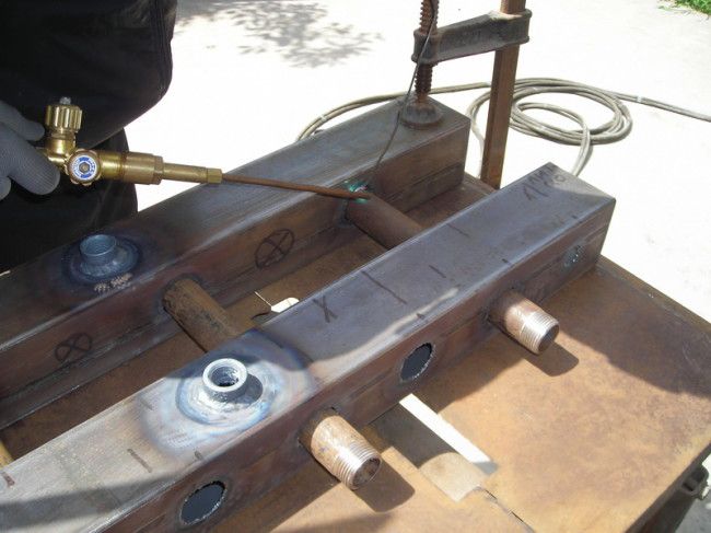
For greater reliability, the main distribution manifold in the water-type collector heating system must be made of metal. For this, pipes of both square and circular cross-sections can be used. The first is preferable, since the installation of the nozzles in them is much simpler.
To do this, you need the following tools and materials:
- Pipe for the main heat of the collector heating unit. Its dimensions should correspond to the calculated ones;
- Nipples for distribution of coolant along the contours. They are made of tubes of circular cross-section with diameter from 16 to 25 mm depending on the parameters of the system;
- Stop valves - ball valves for each circuit;
- Tools: welding machine, angle grinder (Bulgarian), measuring tape, level.
First, the main body of the comb is made by hand for collector heating. On its surface with a welding machine make through holes in which will be installed nipples. Then they are welded, and the integrity of the whole system is checked. To do this, you need to simulate the operation of the system. The outlet pipes are sealed, and the inlet of the future collector heating of the private house is connected to the water supply. With the help of pressure gauges, the operating mode of the system is set and the absence of leaks in the design is visually checked. The next step is gradually increasing the pressure to the maximum design. Only after carrying out such tests it is possible to install collector groups in the heating system.
It is best to use pipes with a wall thickness of 1 mm. For continuous operation, it is recommended to paint the surface of the collector with a special paint.
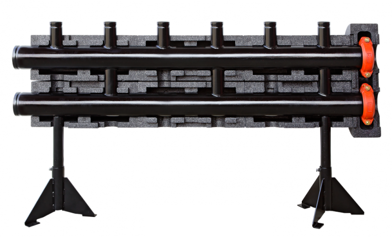
Ready-made collector heating constructions
The optimal option for organizing the collection of large two-story houses is to purchase prefabricated combs. They differ from self-made by greater reliability and precise characteristics, which is important in any system.
However, their high cost should be taken into account. It directly depends on the number of connected contours, the diameters of the inlet nozzles and the geometric dimensions of the collector.
Installation of these components in the heating circuit of the collector type of a two-story house will help to optimize the operation of the entire system. Along with this, it is necessary to take into account possible heat losses, since the comb has a relatively large area. To minimize them, it is recommended to insulate the surface with mineral wool.
In the video, you can see the instructions for making a collector made of polypropylene pipes:
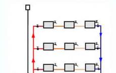
The peculiarity of collector heating is that each heating device is connected to the heating system individually. With this connection, you can adjust the temperature of each radiator, you can turn them on and off individually. The collector (comb) in this scheme is the key node. It is a segment of a thick pipe that has one input and several outputs. To the outputs are connected small circuits, the heating of which can be controlled. If a small circuit consists of several heaters, they are already switched in series.
Advantages of the collector heating: independently, and centrally, it is possible to control each element or group of elements of the heating system. Since each branch from the collector feeds one or more radiators, pipes of small diameter are used, which can be hidden in the screed.
Disadvantages also exist: a large flow of pipes hidden in the floor of the pipe should not have connections, since the connections are possible places of leakage of the coolant. If the pipes are not hidden, then because of the large number of them, the aesthetic appearance of the rooms deteriorates.
Collector heating for a country house
Collector heating represents a system in which wiring is laid under the floor. As a rule, it is made of metal-plastic pipes, which are easily bent and have no joints.Advantages of such wiring
1. The lower connection of the radiators, thanks to which all pipes pass under the floor.
2. A heat carrier with the same temperature is suitable for each radiator, because the motion occurs from one collector.
3. Installation of thermal head allows each room to maintain a different temperature thanks to the panel with settings.
4. It is possible to lay pipes from the first floor to the second one.
5. The collector can have up to 12 outputs and inputs.
It is noteworthy that the floor (under which the pipes are placed) can be, as it is poured with concrete, and made of parquet. Pipes can be arranged in a chaotic order, the main thing is not to forget where they are located (so that during the installation of the floor do not break them with screws).
General principles
Collector heating refers to a heating system in which a heating medium is supplied to each heating device or a small group of appliances by a personal circuit, and all circuits are connected to two common collectors: the supply and the receiving one.The collector is the coolant distributor along the contours. It is a short section of a relatively large diameter pipeline with a group of bends. Each of them is the flow or return line of the personal circuit of the heater. Only supply lines of contours are cut into the supply manifold. In the reverse - only the reverse. The collectors themselves are connected to the corresponding lines of the heat source. In general, the source of heat is a hot water boiler.
The collector way of wiring is intended primarily for organizing the heating system of a country house and other private households. The construction of such a system in an apartment building with a centralized heating system is not possible in view of the lack of a single sufficiently powerful heat source in a single apartment. The distribution of heat from one selective riser across all rooms will result in the fact that all other apartments will not receive the same amount of heat by the same riser. It may even not suffice for the apartment in which the heating system is being converted. The introduction of such changes in the centralized heating system is simply forbidden and threatens with large fines and bringing the wiring back to its original state at the expense of the owner of the dwelling.
The exception is the latest new buildings, many of which have a centralized heating system in the apartment in the form of a single point of connection, and the premises are rented without performing finishing works. In such apartments, any wiring of a heating system, including a collector type, can be performed. But even under these conditions, assembly of the collector-type wiring is possible only taking into account the implementation of special measures.
Collector type of wiring is applicable not only in single-story construction. If there are 2 or 3 floors in a country house, its own collector group is located on each floor of the building, and the coolant is supplied from the common boiler to the risers. In the presence of autonomous heating in the apartment, nothing hinders the use of the collector type of wiring.
Structural design
The collector wiring is performed before the beginning of the finishing works before pouring the concrete floor of the floors. On a trajectory as close as possible to a straight line, the pipes are fed in the floor thickness to separate heating devices or their groups. The bundles of pipes diverge from a single center like rays, so this kind of wiring is also called beam.Optimal collector group to place in the central part of the floor. It is placed in a built-in wall or an overhead cabinet. From it, down to the floor, as many pairs of pipes as the contours will be arranged. Central placement reduces the length of the contours and allows you to make their length about the same.
Each circuit is connected to the collector group via its own shut-off valve. This makes it possible to withdraw part of the devices at any time without affecting the other circuits. Contours can be supplied regulating valves with manual or automatic control. Automatic control valves with servo drive are controlled by the signals of the temperature sensors of the coolant or air in the room.
Collector wiring is always performed with forced circulation of the coolant. For simple systems with a small length and approximately equal hydraulic resistance of the circuits, the circulation provided by the boiler pump is sufficient. Systems can also be used when a part of the circuits is pumped by a boiler pump, and some have their own circulation. So, for radiator heating circuits, the pressure of the boiler pump usually suffices, and the contours of the water-heated floors due to much greater hydraulic resistance without their own circulation will starve, as the coolant will go along the path of least resistance-through the radiator circuits. The circuit equipped with a circulation, shut-off and regulating valves functions as a separate system.
Due to its specific geometry, when the pipes are lowered into the floor screed, they rise to the radiators, the manifold wiring is prone to the formation of air plugs. Installation of air vents in such systems is mandatory. Manual or automatic air vents are installed on each radiator and on the manifolds.
It is not necessary to make contours in the extent of more than 60 m. Especially when installing warm floors. Otherwise, the temperature drop and the hydraulic resistance in the circuit are too high. By default, the consumption of pipes for a warm floor per 1 m of heated area is 5 m of the pipe. This means that one circuit is able to heat 12 sq.m. sex. When it is necessary to heat a large floor area in one room, it needs to be divided into sectors, each of which will be heated by its own circuit. With the correct calculation and competent execution, it becomes possible to completely refuse radiator heating.
Along with a purely collector wiring, a mixed circuit is often used. The entire heating system is divided into several circuits. Within a single circuit, the devices are connected in traditional ways, sequentially with a single-pipe circuit or in parallel with a two-pipe system.
Collector group
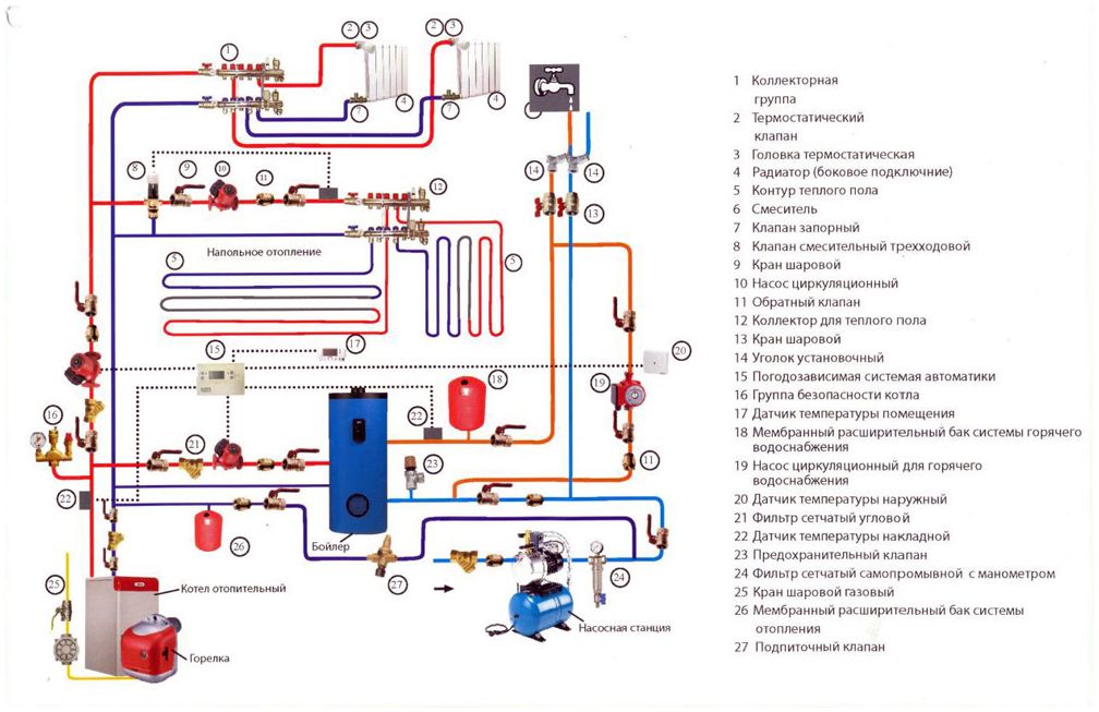
Collectors of factory manufacture are delivered with the possibility of connecting from 2 to 12 circuits. The supply and return manifold are located on the mounting rails attached to the wall.Depending on the purpose, the collector group, in addition to the combs themselves, may include:
additional collectors for supplying the radiator circuits;
flowmeters;
automatic control valves;
Crimping fittings for connecting to pipeline contours;
circulation pump;
mixing unit;
Shooting gallery;
a three-way valve with a servo drive and a temperature sensor;
air vent;
stop valves;
thermometer;
manometer;
drain cock.
The collectors of the power supply of the radiator circuits are installed at the inlet of collectors of the contours of warm floors up to a three-way valve. The circulation in the radiator circuits is provided by the boiler pump.
Flowmeters can be installed at each outlet of the feed manifold. This device shows the flow of coolant through a specific circuit in liters per minute. It allows you to set the desired flow rate in the nominal mode.
The automatic valves installed on the return manifold stop circulation in the circuit when the set temperature is reached and resume it when the temperature drops.
To connect to the circuits on the collectors, there are euro-cone outputs of 1/2 or 3/4 inches.
Collector units designed to supply circuits of warm floors are often supplied with a common circulation pump. In this scheme, the pump pumps the coolant from the return manifold to the supply.
A three-way valve with a servo drive regulates the supply of hot water from the boiler to the circulating pump of the collector group, depending on the water temperature in the return manifold. The bypass output of the three-way valve connects the flow and return of the boiler directly, bypassing the collectors of the warm floors.
Pipes for manifold distribution
The pipes laid in the floor screed are subject to the same requirements as for pipes of water-heated floors. The whole section of the contour, filled in concrete, should be made of a single piece of pipe. Joints are not allowed. Each connection is a potential leak. Their removal will require disassembly of the floor covering and concrete slab. Therefore, for the collector wiring only suitable pipes, supplied a large footage in the bays.The pipe must be strong enough to withstand contact with concrete, and it is easy to bend along the arc while maintaining a through section. It is convenient when the bent pipe holds the mold after removing the bending load.
The pipes must be in contact with the hot coolant and maintain its excess pressure. In country houses, where the source of heat is its own gas boiler, the heat carrier is fed to radiators with a temperature of about 60 ° C and an excess pressure of 1.5 bar. For warm floors, the temperature of the coolant should be up to 40 ° C. When using solid fuel boilers, there are often deviations from the nominal modes. This should be taken into account when choosing pipes for manifold wiring.
In each circuit only one or a small group of heating devices is connected, so a large diameter pipe is not required here.
For the layout of circuits in collector heating systems of country houses and apartments with autonomous heating, pipes from polyethylene molecular cross-linking, reinforced with aluminum foil. PEX-Al-PEX pipes have a permissible operating temperature of 95 ° C and a pressure of up to 10 bar. Pipes of the most running size have an outer diameter of 16 mm and an inner diameter of 12 mm. They are supplied in coils of 200 m length. They are easy to bend with a fairly small radius. In the bent state, they do not lose shape. Manufacturers guarantee the service life of such pipes 30-50 years. These pipes, depending on the manufacturer's firm, are offered at a price of 1-2 dollars per running meter. Connecting these pipes to the radiators and the collector group is performed by compression fittings.
For direct connection of the collector wiring to a centralized heating system, pipes with a large margin of safety should be used. You can not influence the parameters of such systems, and the role of the human factor can not be underestimated. Stainless steel corrugated tube can withstand temperatures up to 400 ° C and operating pressures up to 15 bar. This allows a brief increase in pressure to 60 bar. These pipes can be bent by hand with a bend radius of 50 mm. The service life is unlimited. A pipe with a nominal internal diameter of 15 mm is supplied in bays of 50 m and is offered at a price of 5 to 10 dollars per meter. For the connection of stainless pipes, crimp fittings are also used. The open part of such a pipe requires careful handling. If by connecting such a pipe to the radiator with each cleaning brush with a vacuum cleaner, the pipe will break with time. Metal plastic in this respect is stronger. Stainless corrugated pipe is more suitable for the installation of warm floors. In this operation, the pipe is protected against periodic influences, and its consumption per linear meter of the heated area is less than that of the plastic surface, since its thermal conductivity is much higher.
Similar characteristics have copper pipes for underfloor heating. Copper pipes are considered almost eternal. They are connected to devices and collectors by compression fittings or by soldering. For laying in the screed, it is better to use copper pipes with a polymer coating. When using such pipes, it must be taken into account that in order to avoid electrolytic corrosion, direct contact of copper with steel is not allowed. Copper pipes with a diameter of 15 mm cost from $ 5 per running meter.
Pipes in the screed before pouring with concrete can be fixed in different ways. The simplest way of laying is fixing with plastic clips to the reinforcing bar. In the absence of reinforcement, options are possible. If the floor under the screed is insulated with expanded polystyrene, the pipes are fixed to the insulation with drive clamps. When the screed is made directly on the slab, it is necessary to use clamps with a hairpin screwed into a plastic stopper. Holes for the installation of these collars are drilled with a perforator. Clamps of any type are installed through 300-400 mm and on the bends of pipes.
Pipes collector wiring, which do not participate in the device of warm floors, are isolated. To do this, use shells made of foam polyethylene.
Bypass Valve and Shooter
If there is own circulation or automatic regulation in the circuits, their total hydraulic resistance or coolant consumption can vary within wide limits. The automation of the boiler does not take this into account. To ensure that the boiler pump and the circuit pumps work long and without contingencies, special unloading elements are used. Let's consider possible situations.The electronic logic of the operation of the control valves of one or several circuits determines that it is time to reduce or completely stop the coolant flow through the circuit. The electronics of the boiler, even if it is capable, regulate the pump supply does not know anything about it. The boiler pump continues to pump water. This leads to its overheating, depressurization of compounds and other bad consequences.
To prevent this from happening, a bypass valve must be installed at the collector connection to the boiler feed and return. If the pressure exceeds the set value at the inlet to the delivery manifold, the valve opens and starts to transfer water to the outlet of the return collector. Circulation occurs over a small circle only along the main lines to the collectors.
The bypass valve is installed as close as possible to the manifolds to reduce the inertia of the system and ensure the normal operation of open circuits. When the coolant in the circuits cool down, and the adjusting armature starts to open, hot water will go to the contours immediately, and not after all the water cooled off in the main lines comes off. A large temperature drop of the coolant is harmful, both for the boiler itself and for other elements of the system.
In the presence of its own circulation in all contours of the system, another situation is possible. The flow rate of the coolant in the circuits can exceed its flow through the boiler. As a result, the pressure in the return manifold and in the circuits themselves up to the circulation pumps increases. This reduces the longevity of equipment, threatens leaks and so on. It turns out that another bypass valve is needed, which is capable of circulating water in the reverse direction relative to the first direction.
Even with the correct operation of these valves in different parts of the system, an increased pressure will sometimes be created at times. In practice, they come easier. Instead of two valves, a section of a large-section pipeline is installed, connecting the inlet of the supply manifold and the output of the return manifold. The heat carrier, depending on the currently established differential pressure in the system, freely flows in one or the other direction. This section of the pipeline is called a hydro-gun.
The low flow rate of the liquid in the hydro-gun allowed it to be equipped with additional functions. Such a section of the pipeline is placed vertically. At the top of the gun, an automatic air vent is installed, and in the lower part there is a valve for the discharge of the slurry. To intensify the processes of separating air and slurry inside the shunters, a mechanical grid is placed in the path of the fluid streams.
Some installers take out the pump of the boiler, and the circulation is provided only by the pumps of the circuits. In this case, the boiler pump is installed in one of the circuits. So they try to do without a water gun and a bypass valve. But the problem of high pressure in the reverse circuit does not solve it. In addition, to make such manipulations with new warranty equipment - the occupation is doubtful.
Leave your comment
At present, especially popular projects are those in which heat supply systems for cottages are using collector heating systems. This wiring is also called collector-beam and is the most preferable option among all types of wiring.
We will understand, according to what general principles the system works, which scheme is the most profitable in designing and installing which materials are better to use.
Definitions
The collector (comb) is a type of sanitary fittings that distributes the coolant along the contours of consumers. Simply put, this is a segment of a thick pipe, which has one inlet and several exits. His appearance was facilitated by the complication of heating systems, the spread of floor covering and radiant radiator wiring, the increase in the number of points of heat consumption in the house.
The collector of heating. Click on the photo to enlarge.
The coolant flows through the main pipeline from the boiler room to the floor collectors. They have a number of inputs / outputs, which corresponds to the number of consumers of thermal energy (radiators, convectors, etc.) on the floor.
Unlike the serial connection (with the help of tees), the collector heating system differs by independent connection to each heater. Such a scheme makes it possible to control the temperature mode of each radiator, if necessary, allowing it to be disconnected without affecting other heat appliances. For this, each manifold outlet is supplied with its shut-off valve.
A mixed wiring is possible when several small loops with independent control are connected to the manifold. In this case, a sequential system for connecting the heating devices is used inside each circuit. With a collector, the heating circuit becomes simpler, allowing you to discard seals, additional shut-off and control valves. Using manifolds and collector units, it is possible to significantly reduce costs in the design, installation and adjustment of the heating system.
Pros and Cons of Collective Heating
Recently, the heating system of a country house is often mounted according to the scheme of collector floor wiring or is a combination of it with single-tube and two-pipe systems. Collectors are distinguished by both positive and negative qualities.
Advantages
The main advantages of a collector circuit are the convenience of operation and management of systems of this type. Application of the collector leads to the fact that:
It is possible to control each element of a single circuit centrally and independently of other contour systems. From one point in the house, you change the temperature or completely turn off the appliance or group of heaters in one room of your own choice. But the temperature in other rooms of the house does not change.
Since each circuit from the collector feeds only one or more radiators in the house, the diameter of the contour pipe can be small. Pipe laying is laid in a straight line in the screed between the heater and the collector.
If necessary, the manifold wiring makes it possible to form several circuits having different heating parameters (pressure drop and temperature). For this purpose, the so-called "hydro-gun" is used - a type of reservoir, which is a large container with several nozzles.
It connects and divides the flows of the coolant, ensuring independence for each circuit of circulation. The task of the hydro-gun is to exclude its hydraulic influences on the operation of the other when operating one circuit. At the same time, from the first circuit to the second, heat must be transferred.
Two circuits can be connected in a simpler and cheaper way, but in this case, independently of each other, each of them will be almost impossible.
disadvantages
Collector heating system. Click on the photo to enlarge.
The collector wiring diagram provides for an increased flow rate of pipes, which is much larger than the number of them when connected in series. The difference in the costs of the two systems changes in the larger direction with an increase in the area of the house and the complexity of the configuration of the premises.
Traditional one-or without any difficulties mounted on the walls. Such a layout for beam collector heating does not look very aesthetic.
Pipes in the floor, which are laid in the screed as a liner, must be integral. Any welded or threaded connection is a potential leak. This should be taken into account when installing the wiring, because opening the monolithic concrete to eliminate the leak will later cost too much.
The circuit will have a large total hydraulic resistance due to the use of small diameter pipes. Required forced circulation. The system is volatile, and any power cut-off will cause the pipes in the house to be cold when the boiler is running.
If the house uses several independent heating circuits, it will be necessary to install one circulation pump per circuit. This - additional costs when installing and operating the collector heating system.
General principles of design
There is no single instruction for drawing up a working draft of collector heating systems. In each individual case, heating appliances and equipment are selected individually. But it will be useful to each interested person to get acquainted with several general advice.
The collector scheme is not for a city apartment.
An exception can be considered cases where builders in new homes additionally install in the apartment one pair of valves to which you can connect the heating circuit of arbitrary configuration. In this case, the collector wiring is safely installed. With a common risers for all apartments, the collection system is not possible.
Suppose there are several risers in the apartment and one or two heating devices are connected to each. You want a general collector circuit to be mounted, and install one pair of combs with heat distribution throughout the apartment, disconnecting from all the other risers. As a result, you will get a large pressure drop and return temperature on your sidebar. This will lead to the fact that the neighbors in the riser battery in the apartments will be almost cold. As a result, the visit of the representative of the housing agency is inevitable, which will draw up an act on the illegal change in the configuration of the heating system and will oblige you to make an expensive reworking of the heating system.
The system must be mounted so that the automatic air vent is located directly on the manifolds. This is the best option, because sooner or later in the circuit through them all the air will pass.
The manifold wiring system has many features, but some of them are also characteristic for other types of heating systems:
- The circuit should be equipped with an expansion tank, the volume of which should exceed 10% of the total volume of the heat carrier.
- The expansion tank is best placed in front of the circulation pump, on the "reverse", along the water flow. When using a hydro-gun, the circuit must be designed so that the tank is installed in front of the main pump that circulates the water in the small circuit.
- The choice of the installation location of the circulation pumps in each circuit is unprincipled, but it is better to install them on the return feed. There is less operating temperature. Mount the pump so that the shaft is positioned horizontally. Otherwise, with the first air bubble, the device will remain without lubrication and cooling.
Pipe Selection
To determine which pipes the collector heating system is mounted on, it is necessary to understand the specifics of the collector wiring. Let us remember what can influence our choice.
Heat in the house is a guarantee of comfort. Installed in the heating system of a private house, the heating collector significantly improves its maintainability, allowing replacement and removal of any component without disconnecting the entire heating circuit.
Collector heating can be used both in country cottages and in apartments of multi-storey residential buildings. Collector wiring is installed in houses where warm floors are used to heat some rooms, while others are heated by traditional means of heating - radiators or convectors.
For the distribution unit a special cabinet or box is mounted. It provides easy access to equipment during operation.
Disadvantages and advantages
The collection system of heating has slightly higher cost in comparison with one-pipe or two-pipe schemes due to the need to purchase and install additional equipment and increase the total length of pipelines in the house. However, in general, the laboriousness of mounting increases insignificantly and is compensated by the convenience of operation.
The simplicity of the design allows you to install the distribution center with your own hands. Installed in the house or apartment collectors allow you to separately adjust the heating parameters in each room or ring circuit. A comb with shut-off valves on the fittings significantly reduces the damage from leakage and simplifies repairs.
This scheme compares favorably with most heating systems, although they are cheaper, but they require the entire riser or the whole pipeline section to be shut down, disrupting the microclimate of the premises, and sometimes the entire house. The use of collectors allows you to create a separate ring circuit for each floor of a house or group of heating appliances.
Design features
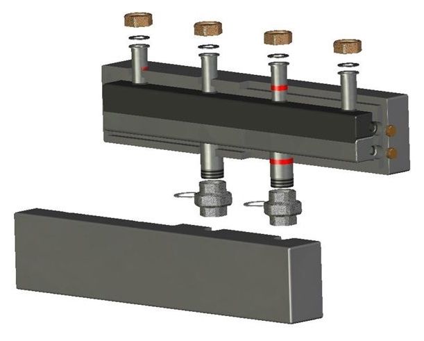
Structurally, the collector for heating is a metal pipe enlarged in comparison with the circulation pipelines of the diameter. It has a group of through holes, to each of which are welded threaded fittings, each of which serves a separate heating device or circuit.
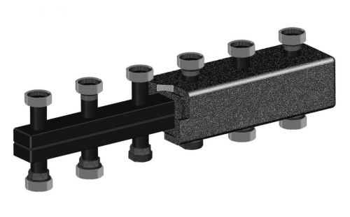
As a rule, the device has one inlet fitting in the end of the pipe and a certain number of output, including the second end of the pipe. For the convenience of placing the assembly in the enclosure and the layout of the piping connection, the collector can be assembled from two or more combs.
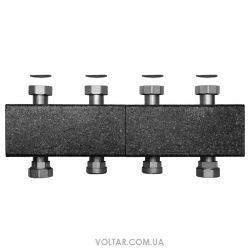
The design of a typical heating collector provides for the presence of two identical elements, fastened by means of connecting brackets. One comb is designed to distribute the flow of heat transfer medium to the heating devices, and the other serves to divert it to the common pipeline.
For the rational use of space, the combs entering the heating manifolds can be installed at an angle to each other and connected by sets of fittings, or pipes made of polypropylene or metal-plastic.
The distributor manifold provides connection to threaded connections of various pipeline valves, the thread diameter of which coincides with the analogous parameter of the comb fitting. The assembly diagram can include the connection of cleaning filters, ball valves and control valves, flow meters and check valves.
Collector group
Together, the combs with the components of the pipeline fittings installed on them are called the collector group. The collector group can be delivered to the customer as a complete and ready to install assembly assembly. It is easy to install it to the owner of a private house within a short period of time using only a universal construction and assembly tool.
Production of a collector by one's own hands
If you have the necessary skills and a sufficient set of equipment, the collection group for heating can be assembled independently. It is convenient to make it from a tube of square section. For this, two pieces of necessary length are cut off, then a round metal pipe is cut, marking is done and corresponding holes cut out in the main pipes. The structure is then assembled, and the joints are welded by welding. After assembly, the seams are cleaned and the product is painted.
An example of a homemade node.
The unit made in the home workshop must be tested for strength and tightness at elevated pressure before the connection. After the testing, you can start the mounted circuit in the work. But a large number of detachable joints significantly increases the risk of leaks, so it is better to give preference to industrial serial samples.
Installation of heating collectors
The distributive collector of water heating systems can be installed manually or with the involvement of professional plumbers, specializing in the installation and maintenance of heating systems. It is only necessary to pay attention to the rigidity of mounting the collector manifold to the base.
The assembly of the unit can be done on a wall, in a special cabinet or metal box, which is a structure of bent sheet metal. In it, special punches are made for holes to pass the pipelines of the system. It can be closed or open type, if there are no special aesthetic requirements to the room where the collector wiring is installed.