Heating of the collector type. Collector heating system: characteristics and design principles
To make collector for heating own hands, you need to pay special attention to dimensions, metal and finish. How to cook than the factory assembly is different from the usual and other interesting, we learn today.
The classic collector of heating is a welded construction resembling a comb. Hence the name, the heating comb.
More often horizontal with branches to one or both sides, depends on the location of the boiler house. If the branch pipes are above, then the boiler is in the basement, above it are radiators, ventilation, warm floor. The lower connections are intended for devices below the boiler room level. Mixed options are also in demand.
Features of the production of the reservoir
It's easier to make a collector with your own hands if you take a ready-made diagram. Fortunately on the Internet, you can find many drawings with detailed and not very explanations. Once you find the right one, prepare the materials.
In this issue there is no unanimity. Some say that there is no better than stainless steel. Others love black steel. Strong and inexpensive, resistant to rust.
The profile pipes will soon be a collector
There are fans of polypropylene. Indeed, it is possible to produce a shunting rifle or a collector from of this material you can, and many are actively engaged in this. But it turns out more expensive and often with defects. Read more in article.

Polypropylene manifold
Experts advise metal. Which, you decide. The main thing is that the alloy should be resistant to high temperatures. The collector works directly with the coolant, both from the feed (the hottest) and from the return flow.
Attentively, study the place of installation. Where the boiler is installed, the capacity of the system, the distance to the wall. All this is necessary to know, then the heating collector will turn out to be qualitative and fit perfectly with the boiler room. You can insure yourself and invite a master who will quickly take measurements and help in technical matters.
What the collector consists of
Conic brackets easily move apart, increasing the mounting length. The subsequent dismantling also will not cause difficulties.
Advantages of factory collectors
Functionality. You can easily equip an autonomous heating system with several circuits.
Service. Collected, put, connected. Air and impurities are removed through special openings.
Efficiency. The boiler house is not idle. Pressure jumps, temperature differences are compensated for by the admixture.
Saving. Thanks to the collector, the boiler distributes heat in full. The costs for seasonal renewal and repair are decreasing.
No matter how hard the engineers are, offering all the new ways of heating, but the traditional water is not going to give up its leading position. This is an efficient and practical way of heating the housing is quite satisfied most of the developers. They are interested, rather, not a cardinal change in the method of heating, but variants of modernization of the traditional water system. Among them is the collector for heating, which replaces one and two-pipe structures. The device increases the efficiency, usability and maintainability of the system.
Collector: device and principle of operation
The unit is an element in the form of a comb, from which the terminals for connecting the heating devices depart. The number of pins can be different. If necessary, the element can be expanded with additional taps. On the collector can be installed drain and air discharge valves, as well as heat meters. The terminals can be equipped with adjusting or shut-off valves, which makes it possible to regulate or cut off the heat carrier flow. The device is installed in the heating system in the form of a collector unit, which includes a return and supply comb, equipped with exhaust valves and associated valves.
The collector heating system functions quite simply. The heat carrier, heated by the boiler to the desired temperature, enters the supply manifold. Here it is distributed between the heaters. To each of them a pipeline is laid, along which the coolant is directed. In the radiator, which has given part of its heat, the liquid partially cools, and through another pipe it enters the return comb and from there to the boiler. This distribution contributes to a uniform heating of the radiators, since a separate feeding pipe is suitable for each of them.

The heat carrier, heated in the boiler, goes to the supply manifold, where it is distributed through pipes suitable for each radiator. The cooled liquid through the return manifold is sent back to the boiler
Note! The distributive comb of the heating system installed on each floor of the heated building allows to obtain floor heating circuits with autonomous control. If there is a need, you can turn off the heating of the entire floor or only a few devices, which significantly simplifies the maintenance and repair of the system. It does not affect the functioning of the entire structure. The use of the collector increases the efficiency of the equipment, since it is possible to install devices regulating the temperature and pressure of the coolant, as well as flowmeters.
The nuances of the organization of such a system
For a low-rise cottage or a private house, the collector heating system is considered to be the most reliable and effective. Its arrangement will cost more than installing two or more single-pipe system. And this can be considered the only significant drawback of the device.
When planning collector wiring, it should be noted that it will not be able to function without circulating pump. In addition, its installation is laborious and complex. It is better to entrust it to professionals, if there is no experience of construction work. A large number of pipes will be required to install the system, since individual layout from the collector to each heating device must be made.
What distributive combs are there?
Manufacturers offer a variety of collector models. Among them you can find devices with the maximum set of elements. The feeding part is equipped with flowmeters that regulate the heat carrier flow in each loop, for a more even distribution. On the return heat sensors are installed to monitor the temperature of each heater. The system automatically controls the heating of each radiator. The cost of such distributive heating comb is quite high.

Collector block with the maximum set of functional elements. The feeding part is equipped with flowmeters that regulate the supply and the head of the coolant. On the return collector there are thermal sensors
You can choose more simple options. For example, a brass element with an inch passage. The device has plugs on the return collector, which allows, if necessary, to install additional devices. There are molded parts and the simplest ones - with collet clamps for metal-plastic pipes. This is the cheapest and problematic option. The device often "suffers" from the possible leakage of the coolant in the valve connection area, which is associated with the rapid wear of the sealant, which can not always be changed.
Folk craftsmen often make their own distributive combs. Perhaps the best of all options can be considered a pipe made of stainless steel of the desired diameter, to which the outputs are welded. But, despite all its simplicity, it is quite expensive. And not only because of the cost of the pipe. You will need to install a lot of additional elements to get the full equipment. Therefore, many use the most budgetary option - a collector for heating, assembled from polypropylene tees, the correct size of the valves, etc.

The most accessible and low-cost collector. Self-assembled from polypropylene tees, valves of the right size, pipes and other necessary parts
Where is it better to install equipment?
The ideal option is to select the location for the installation of the collector during the design of the heating system. If there are several floors in the building, there is space for each collector block in each building. Most often, a niche in the wall is placed under it, located at a small height from the floor. It must be kept in a room that is protected from excessive moisture. It can be a pantry, corridor, etc.
The device can be fixed directly to the wall, if it is installed in the utility room, or placed in a special collector cabinet. The cabinet is a metal box with a door and a stamping tube, designed to hold pipes in the side walls. Inside the equipment, special fasteners can be provided for the collector unit. You can find a waybill or built-in version of the cabinet.
Autonomous heating systems can be built different ways. One of the most popular types of heating system in the house is a construction with a liquid coolant. Typically, it uses water with special additives. Such a system can have several heating circuits, for example, heating through radiators and through warm floors. To ensure that the water in such a system is distributed evenly - you need a distribution manifold.
Purpose of the heating collector
The absence of a distribution manifold in a water heating system can lead to the fact that water can flow unevenly into different contours of the system. As a result, you will have hot floor and cold radiators, or vice versa.
This can be due to the fact that several circuits can be connected to one outlet of the boiler heating system. The liquid flows through such connections unevenly, as a result of which parts of the premises will not suffice heat. But it is the amount of heat carrier passing through the pipes, the volume and speed of its displacement that determines the efficiency of the heat supply system.

Some home owners are trying to solve this problem by installing additional pumps and control valves. But this only complicates the system and does not always lead to a uniform distribution of the coolant.
Example of heat transfer in a private house
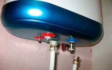
Take for example the heating system for a private house of 100 squares. The device for heating water will be a wall-mounted gas boiler with one outlet pipe with a diameter of ¾ inch.
In the house we have two heating circuits and one circuit that heats the water for domestic use by indirect heating. All circuits are constructed of 1-inch diameter pipes. How to calculate and build effective system heat supply?
First of all, we understand for ourselves that the main reason for poor-quality heat supply is an elementary shortage of the coolant in the system. But the main reason for this shortage is the extremely narrow distribution pipelines.
Thus, to increase the efficiency of the thermal system, that is, to increase the diameter of the distribution pipes, there are two ways:

- When using boilers with built-in pumps, they are connected to a hydro-gun (flow distributor). At the same time, each circuit of heat consumption must be equipped with its own circulation pump. But such a device will only work in a small building. With the increase in heated areas, its efficiency and reliability fall sharply.
- The most reliable way will be to connect the heat source to the water distribution manifold.
The most perfect form of the distribution manifold is called the campanar. With its help, the problem of connecting pipes of different diameters and the volume of the coolant placed is effectively solved.

Let us consider how to create the distribution systems of heat flows by our own hands.
Hydraulic arrow
This is a fairly simple device. It can be made from a piece of pipe with a cross section of three times more than the outlet pipe of the boiler. At the ends of the segment, it is necessary to weld the plugs of the curved shape. In the plugs, holes with threaded threads are then cut. They will serve to discharge air or drain water. In the body of the pipe we drill holes, in which we also cut the threads. To these we will connect the boiler outlet and heating circuits. After that, the body of the shots should be sanded and painted.

Comprehensive distribution manifold
Despite the fact that in building stores there is a large assortment of distribution manifolds of different sizes - it is sometimes difficult to choose a device for your heating system. There may not coincide either the number of contours or their cross-section. As a result, you will have to make a monster from several collectors, which is clearly not the best way to affect the efficiency of the heating system. And not so cheap it will be such a pleasure.
In this case, it is not necessary to believe the stories of "experienced" that the system can work fine even with direct connection to the boiler. This is mistake. If your heating system has more than three circuits - then the installation of the distribution manifold is not a whim but a necessity.
But in the absence of a distribution manifold that is suitable for you in terms of parameters, you can do it yourself.
We make the distribution manifold with our own hands
The distribution manifold project is developed based on the number of heating circuits in your system. Evaluate where your heating boiler is located, what it has an inlet and outlet connection, how many heating circuits or circuits indirect heating will be used in the heating system. Perhaps you are planning to increase the number of circuits in your house, for example, add another room next year. A distribution system can also be connected solar collectors, heat pump and other devices. We also consider all systems distribution heatincluding warm water floors, heating radiators, fan coils and so on.
We compose the scheme of our heating system, considering that each circuit has a supply pipe hot water and a return pipe.
During the design of the system, do not forget to locate additional equipment, such as the expansion tank, valve automatic replenishment, a drain cock and a faucet for filling the system, a group of thermostats and so on.
Produces spatial design, that is, determine where and where our pipes will be connected to our distribution manifold. Practice suggests that on the ends of the collector, the connections for connecting the solid fuel boiler and for indirect heating are usually mounted. If you have a wall-mounted gas or electric boiler in the system, it hits the top or also the end.
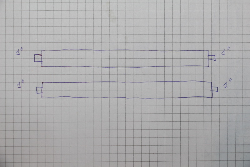
Based on the available information, we draw up a drawing of the future distribution manifold. It is convenient to use millimeter paper. The distance between the nozzles should not be less than 10 centimeters, but they should not be spread more than 20 centimeters. For one heating circuit, the distance between the feed nozzle and the return connection should not be less than 10 centimeters. It is desirable that groups of branch pipes of the same contour be visually distinguished.
We design a collector
The following figure shows an example of a manifold design where six heating system circuits will be connected.
At the first stage we draw two rectangles. This is the actual supply manifold and return collector.

On the collector taps, we design the connection of a boiler and an indirect heating boiler. Do not forget to put in the drawing the parameters of the cross section of the future nozzles.
We design connection of heating circuits and additional heating boilers. Do not forget to put the cross-section of pipes and the dimensions of the nozzles. We sign all the designed nozzles.

At the next stage we design additional equipment connection. In our case, this is an expansion tank, a drain cock, a protective block, a system thermometer. Note that the coolant flow paths are highlighted in red and the return circuits in blue.

It was a draft drawing. We check its correctness and transfer it to the new sheet of paper. It is on the basis of this project that we will create a separate distribution manifold.

Make the distribution manifold
We calculate the material necessary for the production of the reservoir. The easiest way to do this is in Excel spreadsheets. At the same time in this program, you can calculate the cost of materials needed to make the device. We acquire the necessary raw material and prepare tools for self-made.

The raw materials for the main parts of the reservoir will be ordinary or square pipes. We make the necessary markings on them, using calipers, ruler and core.

Using a gas cutter, make holes for the nozzles.

We insert nozzles (pieces of threaded pipe) into the seats.

We fix fittings by welding. First, in black, and then scald all around the perimeter.

Also weld to the body brackets for mounting on the wall.

We clean the welding places from scale and rust.

The entire structure is treated with a degreasing compound, covered with paint and varnish.

The paint fully seizes in two to three days and our disposal is independently manufactured distribution manifold. Now it only remains to install it in place and connect to it all incoming and outgoing circuits.

The system with the distribution manifold will work much more efficiently than simply piling up the heating pipes
In order to catch all the nuances of independent production of the distribution manifold and the scope of its use - we recommend that you watch the training video.
Distributive heating manifold: video
The construction of a heating system in private homes is not easy. And if you approach it with all seriousness, you can create comfortable temperature conditions in the house without spending a lot of money for the purchase of thermal resources. So, most often people give their preference to collector nodes, with the help of which it is possible to perform heating strapping of any complexity and configuration. What is the collector heating system and how to assemble it by our own hand - in our article.
Design features
Collector system Heating has a lot of advantages. It provides even heating of the room, and besides, by means of such equipment it is possible to increase or reduce the volume of supplied heat energy in a single room. And this, in turn, allows you to reduce the cost of acquiring energy resources. Moreover, by equipping the collector for radiator heating with a thermostat, it is possible to control and regulate the temperature conditions, which ensures better and at the same time economical heating.

Before you start assembling the collection system of heating a private house with your own hands, you need to familiarize yourself with all the necessary information regarding the configuration of this unit and the features of its installation.
Features of the device collectors
- Each of the comb taps (this is how the builders are called) is equipped with a ball valve, which allows, if necessary, to cut off the heating devices without affecting the overall heating system.
- Distribution manifold heating, made by own hands, is tied with one- or two-loop highway.
- The distribution of the heat circuit from the collector unit is carried out either in the floor surface or in the wall covering, after which the heat exchangers are connected.
- In the event that the thermal circuit is located in a concrete screed, the radiators must necessarily be equipped with Mayevsky cranes or special valves to drain air from the system.
Using a gas or electric boiler for piping, both the upper and lower connections of the heat pipeline can be performed, whereas for solid fuel heaters, only the side one can be made.
VIDEO: Installation of collector heating radiators
Types of connections
The heating distribution manifold, made by hand, can be used with several types of heating units.
Heating "underfloor heating"

If you approach the calculation of the heating system with all seriousness, you can do without the wall radiators. How? Simply - carrying out the heat main directly on the floor surface. The very contours fit into certain schemes: snake, snail and double snake. Despite the fact that many are accustomed to centralized heating, this option can easily become the main heating of the house, regardless of the area of the premises.
Radiator heating
To this option of heating, the distribution blocks are connected from the side, from below, from above, diagonally (input from above, output at the opposite end of the battery from below). In most cases, the lower connection is used. Firstly, the pipeline is not visible, because it is hidden in the floor, and secondly - for the same reason, not only heat exchangers are heated, but also the floor itself.

The beam scheme
Some homeowners carry out the layout of the thermal circuit under the skirting boards, which excludes the possibility of heating the floor surface.
Solar heating
A new and not so common way of creating comfortable temperature conditions in the house. True, it requires the availability of special equipment. But, again, if you correctly compute the calculations, you can perform the installation of a solar heating system. Yes, as the main source of heat energy this method is not good, but as an additional - this, please.

Assembling the Collector Assembly
Before making a collector for heating by one's own hands, it is necessary to determine what type of pipeline will be used for the heating circuit binding.
There are several main types of pipes that can be used to heat private houses, as well as apartment buildings:
- Stainless or galvanized pipes. They have a lot of advantages in comparison with other models, but at the same time their cost is extremely high, so not all homeowners can afford such an expensive pleasure.
- Pipes of cross-linked polyethylene. The cheapest option and the most not reliable. Of course, it can be used to bundle heating units, but its lifetime is extremely low.
- Polypropylene. Comparatively inexpensive and very high quality material from which pipes are made. And with proper installation the service life of such pipes reaches half a century.
- Metalloplastik. More expensive material, which is also widely used as an element of the binding of thermal systems.
Consider how to make a collector made of polypropylene with your own hands. Moreover, the type of material does not influence the functionality of the comb.
Let's start with the distribution of contours

Experienced experts advise to take separate trunk lines to such heating devices:
- installation of "warm floor" with the use of hot water as a coolant - for each room on one separate highway;
- heating of rooms, the temperature conditions in which differ from other rooms, regardless, in which direction;
- warming up a single floor or wing of a house.
Now with regard to the geometric dimensions of the comb, the device should be such that it can easily be placed in a niche of the wall covering and at the same time is easy and accessible in adjustment. The most optimal distance between the taps is 100-150 mm, and between the supply and return collector blocks - 200-300 mm. Of course, everything depends on the concrete case, and you can change these dimensions. But remember, you should be comfortable to use this device.
The piping for connecting the heat exchangers is made ½ in diameter. For the same comb, a 1-1 / 1-inch pipe is taken, which matches the diameter of the heater's nozzles.
Let's move on to the assembly
To make a polypropylene heating manifold, you will need a special soldering device. If your tool does not have one, you can rent it from a specialized store.
VIDEO: Installation instructions for floor collectors and radiator heating
The comb is made from scraps or pipe remnants, using fittings for its binding. For the supply and return of the collector installation, a Ø32 mm pipeline and 32/32/16 mm tee connections are used which are soldered to each other by means of the apparatus.
One end of the pipe is equipped with a 32/32/32 tee, to the bottom of which we mount a drain cock, and to the top - a vent valve. The other end of the comb is equipped with an inlet valve, to which a supply or return pipe is connected, looking for the heating element.
Taps of 16 mm on the feed are equipped with shut-off valves, and on the return - with a flowmeter. The distribution block is located in a special niche in which a collector cabinet for heating is inserted.
Correctly executed layout of the collector unit will ensure comfortable temperature conditions in your home.
VIDEO: Collector heating
From the series connection (using tees), the collector heating system differs in that each radiator has its own piping. This allows you to adjust the temperature for each battery, and if necessary, then completely turn it off. The key element of the system is the collector (you can see it on the photo), which is also called a comb. The design solution of this device is a segment of a thick pipe, which has one input and several outputs.
In a number of cases, in addition to the serial or collector wiring, a mixed version is used. Several small circuits are connected to the comb, each of which can be controlled independently, but within the circuit itself, the radiators are connected in series.
Advantages of the collector heating system
If the heat distribution system is used for collector distribution of heating systems, the advantages are obvious - they are mainly related to the convenience of management and operation of the structure:
- each element of the heating circuit is controlled independently and centrally. This means that the tenants of the house, being in one place, have the opportunity for any room to set the desired temperature or completely turn off one radiator or group of appliances;
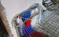
- due to the fact that each line from, supplies the heat carrier only to one heating battery or to their small group, smaller diameter pipes can be used. In fact, the liners are most often mounted in the screed in such a way that the distance between the collector and the radiator is minimal.
The heating collector circuit, if necessary, makes it possible to create several circuits with different heating parameters, with a difference in temperature. In this case, a hydro-gun is used, which is a kind of a collector, or rather a pipe with a sufficiently large internal volume.
![]()
It is mounted in an unusual way, as a result of which a kind of short circuit is formed between the feed and the return. The heating boiler heats the water in a continuous mode in the primary circuit, and it slowly moves inside the hydro-gun. As a result, the coolant is sampled at a different distance from the tapping into the feed and return pipes.
Due to this, it is possible to obtain various parameters of the temperature and pressure of the coolant. Usually this kind of collector is used with simultaneous use of both batteries and heat supply system "warm floor".
In this case, the values of temperature and drop will be different on the inset of each circuit.

But in the case when a collector heating system is created, the circuit of which contains in its circuits own circulating pumps, such a parameter as the drop can be ignored. It should be noted that there may be a simpler technical solution for the sequential connection of two circuits, but then each of them will be difficult to use independently of the other element.
Disadvantages of the collector heating system
Collector system in addition to the advantages inherent and disadvantages:
- the consumption of heat energy is much greater than in the case of consecutive connection. The larger the area of the room and the more complex its configuration, the greater the costs;
- one- or two-pipe heating structure can be mounted on walls without problems, but when it is planned, it is impossible to place the connections in the same way because of unaesthetic appearance and large over-expenditure of materials;
- the laying of contours in the screed has its drawbacks, since the pipes in the floor can not have welded or threaded joints, otherwise they will become places where leakage is likely. Unseal concrete screed to eliminate the problem can not be called a pleasant occupation;
- the hydraulic resistance of the heating circuit in the sum will be very large, especially if small diameter pipes were used. The use of circulating pumps is necessary, since there is not enough insignificant difference inherent in the gravitational heating system;
- when the collector system of heating a private house provides for the use of not one but several independent circuits, it is necessary to install the same number of circulation pumps as laid over the building of large rings. As a result, costs increase not only at the stage of system installation, but also during operation (read also: "");
- availability forced circulation Liquid heat carrier leads to the fact that it becomes volatile. In the absence of electricity, the heating system will not be able to function in the required mode, since when pumps are stopped complex scheme Heat supply will simply be a useless pipeline.
The basic principles of drafting the layout diagram
When the collector heating distribution is designed, all necessary equipment are selected based on specific tasks, but there are several recommendations from specialists:
- In urban apartments categorically it is not recommended to use collector systems. The fact is that it is problematic to implement such a scheme in a multi-storey building (read: ""). If you disconnect the heating devices from the risers and mount several combs, the heat supply in your own premises will not be affected, but in the neighbors whose batteries are powered on the same branch, a significant drop in the drop and return temperature will lead to a cold in their apartments.
As the radiators become practically cold, the neighbors' reaction will be immediate - it is a visit of employees of the housing organization, drawing up of a corresponding document about unauthorized and unacceptable change of the heating system configuration. The result is unambiguous - an involuntary conversion, which will cost a considerable amount.
- Automatic air ducts are mounted directly on the combs.

There are other features not only in the case when collector heating with their own hands, but also heating systems of other types:
- in the circuit must be present expansion tank, the volume of which can not be less than 10% of the total volume of the coolant. It is possible that he was more, since there will be no adverse consequences from this. Since the cost of the expansion tanks is quite affordable, it does not make sense to save on them;
- the expansion tank should be stirred on the return flow of the coolant in front of the circulation pump. When a water gun is used, the device is placed in front of the main pump, which circulates water in a small circuit. This location is explained by the fact that membrane tanks To avoid fluctuations in pressure in the circuit, it is necessary to install where the turbulence of the water flow is minimal;
- as for the installation location of the circulation pump in a single circuit, this does not really matter, but finding it on the return will increase the life of the device due to a lower operating temperature. The pump is placed in such a way that the shaft is located strictly horizontally.
Selection of pipes for manifold systems
When a collector heating system is created two-story house or own building of any number of storeys, in order not to leave connections inside the screed it is desirable to purchase a pipe in the bay.
In addition, the pipe must be flexible, resistant to corrosion and have a long service life, so that soon there is no need for repair. With regard to heat resistance and tensile strength, the requirements for these parameters depend on the operating parameters of the heating structure. For a private house it is 1.5 atmosphere and temperature regime for radiators in the range of 50-75 degrees, and for warm floors - 30-40 degrees.

Rare, but all the same, sometimes a collector heating circuit is installed in multi-storey new buildings. In such cases, the determining values are the working pressure of at least 10-15 atmospheres and the temperature is 110-120 ° C.
Selection of pipes for apartment buildings
Best for apartment building a corrugated pipe made of stainless steel. On the parameters it fits perfectly. For example, the Korean Kofulso pipe can be operated at an operating pressure of not more than 15 atmospheres and a temperature of 110 ° C. The fracture pressure of this product is 210 kgf / cm².
This type of pipe has good flexibility, and the bending radius of them is equal to the diameter of the product. Assembling the connections is simple: to do this, the pipe is inserted into the fitting and fixed with a nut that holds the corrugated surface due to the presence of a silicone sealant.
Selection of pipes for the cottage
Stainless steel does not belong to cheap materials and, if a collector heating of a two-story house is projected, it is possible to save on pipes for the heating system (read also: ""). Often for beam distribution use cross-linked polyethylene, for example PE-X. These products are supplied in coils. The length of the pipe is 200 meters, it withstands a pressure of 10 kgf / cm² and a temperature of 95 ° C with a brief increase to 110 ° C.
For the installation of such pipes, fittings are used, which are plastic or brass fittings with a retaining ring that is put on the pipe. Cross-linked polyethylene has a special feature - mechanical memory: after stretching with a special extender and inserting into the lumen of the union, the pipe will densely tighten it after a short time. Additional locking will be provided by the locking ring.
More about the collector heating system on video: