Types and ways of connecting the distribution manifold. The device of the collector in the boiler room for heating
The distribution manifold is installed in the boiler room and is a very important device for efficient heating at home. It functions according to the principle of distribution of the heat transfer medium between all circuits to supply it to the final heat recovery points and takes into account all non-standard characteristics for each heating branch (different requirements for the temperature conditions of all connected hydraulic systems).
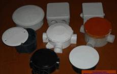
![]() Collectors can control and connect up to eight branches heating system residential buildings and production facilities. it makes it possible to simplify the system and there is no need to install a large number of pipeline connections and assemblies. To the steel outlets of distribution manifolds with the help of special fittings and connecting parts it is possible to easily connect pipes from various materials - propylene, copper, metal-plastic, etc.
Collectors can control and connect up to eight branches heating system residential buildings and production facilities. it makes it possible to simplify the system and there is no need to install a large number of pipeline connections and assemblies. To the steel outlets of distribution manifolds with the help of special fittings and connecting parts it is possible to easily connect pipes from various materials - propylene, copper, metal-plastic, etc.
Contour of the boiler house is a separate branch of the system, which has coolant parameters that differ from the filler at the boiler outlet. A typical boiler house project a private house Contains three contours in the design:
- a network of pipes and radiators for domestic hot water heating;
- a warm under floor heating system;
- boiler connection for reception hot water.
The boiler constantly gives an output temperature of 80 ° C, but the efficient operation of the various connected branches requires a different thermal regime. To operate the heating circuit the temperature of the coolant is needed from 60 to 80 ° C on the forward and reverse lines, and the coolant flow rate is constant. For warm floors, a heat carrier with a heating index of 40 to 45 ° C with the same flow regime is needed. For a boiler, the temperature should be kept within the range of 60 to 80 ° C, and the flow rate is variable from zero when waiting and until full at the time of abstraction.
With the help of the group installed pumps and mixers are prepared and maintained the required temperature for the operation of all circuits. In addition to this separation of modes, the pump-mixing group can support various subsystem requirements in circuits. An example of this is the separation of the heating circuit in residential and utility rooms. The branch of the warm floor can be divided into subsystems of different floors. All lines may have different requirements for temperature and on-time.
In heating systems with a boiler room collector it is necessary to have a circulation pump, reducing the range of difference in temperature at the inlet and outlet and making the heating more qualitative. All bends of the collector are supplied with their own ball valve, which helps to cut off the operation of any circuit without affecting the heating system as a whole.
Typical collector device
 The boiler house collector is a rather large distribution center, in which many working units are connected, usually made of pipes with a diameter of 100 mm. Usually in its composition provides for the installation of two combs to distribute the coolant and collect it at the exit from the system. The feeding comb is supplied with pumps to improve circulation, and the receiver is equipped with cranes. It is mandatory to put pressure gauges and temperature sensors. With the help of such a device, it is possible to civilize the supervision of heating the house.
Devices in the construction of a typical boiler room collector:
- a mixing valve for selecting the coolant temperature;
- circulation pump to increase the pressure in the system;
- hydraulic separator;
- comb in the boiler room;
- automatic weather-dependent;
- expansion tank;
- expansion tank of the hot water supply circuit;
- pressure gauges;
- devices for trapping and removing air bubbles;
- couplings and fittings for switching to different pipe diameters;
- devices for heating the heating;
- group of devices for safe operation of the boiler;
- automatic control of contours.
Description of the purpose of each device
Two-way and three-way valves

In system collector heating boiler room thermal device controls the temperature of each coolant, arriving at the desired highway. If the indicator is not correct, the liquid supply is stopped by closing the valve.
In the heating system, the thermal device controls the liquid in the circuits according to the specified parameters. If the value is not correct, the valve closes and the liquid supply is completed.
The low flow rate of the valve allows it to feed water without jumps, in a smooth mode. Walkthroughs the valves must be periodically removed for cleaning, so it is better not to weld the joint. Two-way valves are reliable and fairly common, but the limitation for their control is the size of the area of the house, which should be no more than 200 m2.
The three-way valve works by the principle of mixing the coolant from direct and reverse feed inside it in a chamber with a perpendicular partition. It regulates the supply of water from two mains and this helps to change the temperature of the liquid to the desired value.
The three-way valve is considered a universal device, its installation is shown when connecting a large number of circuits in a complex heating system. A failure in the heating of the boiler room can occur if cold or hot water enters the system, since the capacity of the valve is very high. Even a small extra turn of the crane can lead to a temperature change in the main.
The pump-mixing device
Adjusts the water temperature in each individual circuit. Includes mixing valves, pump, stopcocks and a group of test and measurement sensors. Some branches, such as a boiler and a pool pipe, do not require the connection of mixing valves. Installation is usually carried out on the manifold manifold in the boiler room.
Hydraulic arrow
Hydraulic separator in the boiler house collector performs several operations at once:

Application of the distributor improves the efficiency of the boiler plant in a private house. If the boiler capacity exceeds 50 kW, then its installation is considered mandatory.
Automatic weather matching

Weather sensors allow you to set the optimal value of the water temperature in the system depending on the temperature in the street. Such electronic devices allow you to save fuel oil due to rapid response to sudden weather changes, sometimes such savings can reach up to 20%.
If you do not put weather sensors, then the user will have to adjust the working power independently, which is not always effective due to the lack of a person at home. In addition, this adds trouble to the owner.
Expansion heating tank
It is installed in order to compensate for the expansion of the volume of the heat carrier when it is heated. Such an increase without such a device can raise unwanted pressure in the main. At the tank device the head in all mains remains unchanged and is consciously regulated by a complex pumping system. Calculation of the tank volume is carried out at the stage of designing the house heating.
Expansion tank for hot water
This capacity regulates the expansion of the hot liquid for domestic needs when the volume increases by heating. it allows to maintain the working pressure within the boiler, which will not allow the emergency shutdown of the water heater caused by the indication in the boiler safety device.
Boiler house comb
 Collector heating involves the execution of a comb of a larger cross-section (diameter) than the main branch from the boiler output to the installation site distribution manifolds heating.
This is done in order to reduce or completely exclude interaction when several pumps of different mixing groups operate, allowing to ensure a uniform supply of water to all circuits. The comb in the collector is always arranged, if there are more than two heating branches.
Heating water make-up device
 The amount of liquid in the heating system usually decreases even in closed systems. This can occur because of the depressurization of the pipeline in the event of holes, cracks, breach of joint sealing. Most often, evaporation of moisture through the bubble discharge devices or when removing air plugs.
In this case, the pressure in the system becomes low and the boiler switches off when a critically low value is reached. To resume work or prevent similar accidents, it is necessary to replenish the liquid in the pipeline.
The coolant replenishment devices are produced with automatic and manual control. For private housing construction, the use of a manual option is more recommended. To use such a device, the consumer will have, with properly organized heating operation, no more than once in two months. But if there is a depressurization and water flows out of the system, then necessarily need the presence of the owner, which will help prevent an accident.
Boiler safety device
 A safety group is provided in the boiler room collector, which protects the heating main and the boiler from exceeding the standard pressure in case of emergency situations. This group includes an automatic air separator, a safety emergency valve and a pressure gauge of actual pressure.
On the manometer there is a display of the minimum and maximum allowable values. The automatic air trap removes air bubbles from the heating system and prevents the occurrence of air congestion, which makes the operation of the boiler impossible.
Spring in safety valve tuned to the maximum allowable pressure of the liquid in the pipes. Exceeding the indicator above the norm leads to emergency opening of the valve and removal of excess coolant from the heating system. Each valve is equipped with a device for detecting the indicator of its operating state. In addition, it puts a plate with an indication of its maximum limit for triggering.
When collector option heating safety group must be installed in the boiler room. The selection of the components of safety devices and the selection of the power of each of them is carried out at the design stage.
Automatic control of heating
 A fairly expensive device that allows a complete removal of the owner of the house from participation in the heating process. The system with electronic control will achieve the highest comfort and convenience. Automatics will fully assume all control and regulation functions from the beginning of the boiler operation to the end of the heating cycle. With a complex collector heating system in the boiler room, the use of such a complex device is more than justified.
Disadvantages of heating with a collector
There are a number of negative indicators of heating with the collector, namely:
- the variant of the heating system with the collector in the boiler house is very expensive and a large number of devices and control devices make it inaccessible to a large number of consumers;
One of the effective options for upgrading the heating system, allowing it to be more efficient and reliable, is the installation of a collector unit. The device, which replaced the traditional structures of the linear structure, is designed to improve the usability and maintainability of the system. How the collector operates for heating and what features of installation should be considered, we will consider in more detail.
The main purpose of the collector is to distribute the heat flows from the main line evenly, along the system contours and return the cooled liquid to the boiler by means of the circulation. In this case, individual branches of the system connected to the collector become independent of each other.
The device is an intermediate distribution node, the key elements of which are two interconnected parts:
- feeding comb - responsible for the supply of coolant;
- reverse - performs the function of removing the cooled coolant to the heat generator.
Together they form a collector group. From each comb, there are several pins to connect the circuits leading to the heaters.
The number of pins on the distributor can be any, and in case of need the design can always be increased by additional taps
Each outlet of the device can be equipped with outlet valves and a shut-off or adjustment tap. Their presence makes it possible to regulate the pressure inside each circuit and, in case of need of detaching the branch for repair, for example, to block the flow of the coolant.
In order to increase the system's productivity and to be able to control all the heating processes in each room of a heated house, the comb housing is also used as a platform for installation:
- air release valves;
- drain valves;
- flowmeters;
- heat meters.
Principle of operation collector system rather simple. The liquid heated by the heat generator enters the supply manifold. Inside the intermediate assembly, the velocity of the fluid slows down due to the increased internal diameter of the device, it is redistributed between all the taps.
![]()
The internal diameter of the collector is determined by calculation so that the speed of movement of the coolant inside it is not more than 0.7 m / s
Knowing the coolant flow rate, equal to the power of the heat generator, and the speed of water movement, it is easy to find the required cross-sectional area. Only preliminary it is necessary to translate liters in a unit convenient for calculations mm 3.
Through the connecting pipes, the cross section of which is smaller than the diameter of the pipe of the collector unit, the coolant enters separate pylons and moves to the radiators or to the grids of the warm floor. Due to this distribution, each element, which is supplied with a heat carrier of equal temperature, is properly heated.
Having reached the battery and giving away the heat received during heating, the liquid is directed along the other pipe in the opposite direction to the distribution block. There it comes on the return comb, from where it is redirected to the heat generator.

Such a constructive solution, involving the arrangement of separate supply pipes, creates conditions for uniform heating of the radiators
For country cottage a system using a reservoir is rightfully considered to be the most effective and reliable. The only thing that can stop the diligent owner is the cost. After all, the arrangement of such a system will cost more than the installation of a conventional tee-type system.
Types of collectors in heating systems
Collector plants used in the design of closed circulating heating systems are of three types. Depending on the design purpose, the market includes radiator and solar systems, as well as devices equipped with a hydro-gun.
Radiator collector heating
Whichever type of heating is designed in the house, radiators are always present. Therefore, the collectors distributing coolant flows directly to the batteries installed in the rooms are the most popular type.

The distribution unit consists of two interconnected combs: the first directs the coolant to the devices installed in the rooms, the second - draws it back to the boiler
Collectors used in radiator heating, depending on the architectural and interior features of the premises can be connected in various ways.
By the method of connection, the radiator heating system can be made in any of the following variants:
Upper connection;
lower connection;
installation from the side;
conducting on a diagonal.
The most common is the lower connection method. With such a layout, the contours hidden beneath the skirting or floor surface are not so conspicuous. Yes, and calculations confirm that with the bottom connection all the advantages of private heating are fully manifested.
The collector for radiators is equipped with each floor of the house. Install it in the center, masking the device in a niche or in a specially designed for him locker on the wall. The place for installation should be chosen so that, if possible, branches of equal length are fed to all devices.
If it is impossible to achieve equality of the rings connected to the collector, each branch is supplied with its own circulation pump. In fact, all branches connected to the distribution node represent an independent circuit with its own shut-off valves, and sometimes with automation.
A vivid example of a collector scheme of heating are water warm floors.
The manifold layout of the wiring provides for an even supply of heat to all the "warm floors"
Pipes for warm floors are assembled from copper pipes or their plastic counterparts, for connections use integral fittings. In the heating rings are mounted valves, through which regulate the supply of coolant, and if necessary, turn off the "warm floors" from the common heating network.

The collector for the "warm floor" is a design that includes a number of pipe rings, which is laid under the floor covering
Such systems are always equipped with a circulation pump. It is placed in the intermediate collector unit at the entrance to the pipe in the reverse direction.
The number of nozzles at the distribution node depends on the number of rooms, looped on the same comb. The number of collector groups is determined by focusing on the length of the contours. The basis for the calculations is the ratio at which 120 m of the pipeline are assigned to one collector group.
Hydraulic gun - thermohydraulic valve
With the arrangement of powerful and branched heating systems, which are designed in residential buildings with a large area, distribution manifolds equipped with a hydraulic arrow are used. When installing the link on one side, a heating boiler circuit is connected to it, and on the other hand - radiator heating or "warm floors".

The hydraulic arrow is a vertically installed pipe equipped with elliptical plugs at the ends, the main purpose of which is to equalize the working pressure parameters across all contours
The presence of a distributive hydraulic pointer allows solving several problems at once:
- avoid sudden temperature changes in the pipes, which have a harmful effect on the operational life of the system;
- due to the admixture and secondary circulation of a part of the heat carrier, to maintain a constant volume of boiler water, and also to save fuel and electricity;
- if necessary, compensate in the secondary contour the deficit of consumption.
Maintenance of temperature balance is achieved due to the fact that the device allows separating the hydraulic circuit of the boiler from the secondary circuit.

The variant of manufacturing a self-made collector distributor equipped with a hydro-gun, which is made of a steel square tube and equipped with fittings
The optimum operation of the system equipped with a hydro-gun can be ensured provided that each circuit is equipped with its own circulation pump.
Solar collector systems
Devices of this type are chosen for the arrangement of an autonomous aqueduct in non-gasified areas where the level of solar radiation is high enough.

Air combs that function on solar energy work at the expense of the greenhouse effect, transforming sunlight into thermal energy
Design solar installations slightly different from traditional analogues. In fact, they represent a kind of greenhouse, accumulating solar energy. Natural circulation coolant in them is carried out due to convection currents and under the influence of fans attached to the absorbing plate.
The distributor absorbing the sun's rays is a small flat box covered with a black absorbent plate. This heat-absorbing plate also accumulates heat. The accumulated heat is transferred to the heat carrier, in the role of which air or liquid circulating through the pipes can act.

The main purpose of the solar collector is to direct and redistribute the energy of the Sun to everyday needs and needs
On sale it is possible to meet mobile collector systems working on solar energy. Their design is arranged so that mirrors and heating elements "follow" the movement of the sun, so that the energy of the Sun is absorbed to the maximum.
But because of the high cost of equipment, the use of solar installations as the main source of heating in the climate even in the southern regions of our country is unprofitable. That is why they are used more as an additional source of heat in the arrangement of heating systems with the use of solid fuel and gas boilers.
Modifications of distributive combs
Today in the market of equipment there are many varieties of collectors for heating systems. Manufacturers offer as the links of the simplest version, the design of which does not provide for the presence of auxiliary equipment for regulating equipment, and collector units with a complete set of built-in elements.

Collector block, which includes all the necessary functional elements to create conditions for uninterrupted and high-performance operation of the heating system
Simple in execution of the device are brass models with an inch passage of branches equipped with two connecting holes on the sides. On the return collector, such devices have stubs, instead of which in the case of an "extension" of the system, it is always possible to install additional devices.
More complex in the design solution, intermediate assemblies are equipped with ball valves. Under each branch there is provision for the installation of a shut-off adjusting armature. Heaped up expensive models can be equipped with:
- flowmeters, the main purpose of which is to regulate the flow of coolant in each loop;
- temperature sensors designed to control the temperature of each heater;
- automatic air discharge valves for draining the water;
- electronic valves and mixers aimed at maintaining the programmed temperature.
The number of circuits depending on the connected consumers can vary from 2 to 10 pieces.

Regardless of the complexity and multifunctionality of equipment in the production of combs of collector blocks, materials resistant to external factors
If the material is used as a basis, the intermediate prefabricated collectors are:
- Brass - are characterized by high performance parameters at an affordable price.
- Stainless steel structures are extremely durable. They can easily withstand a lot of pressure.
- Polypropylene - models from polymeric materials, although they are not very expensive, but inferior to metal "brothers" in all respects.
Models made of metal, for prolongation of service life and increase of operational parameters, are treated with anticorrosive compounds and covered with heat insulation.

Separating structures made of polymers are used in the arrangement of systems heated by boilers with a power of 13 to 35 kW
The parts of the device can be cast or can be equipped with collet clamps, which allow the connection with metal-plastic pipes.
But experts do not advise choosing combs with collet clamps, as they often "sink" by leakage of the coolant in the junction of the valve. This is due to the rapid failure of the seal. And it is not always possible to replace it.
Collectors are used in single- and double-tube heating circuits. AT single-pipe systems One comb delivers a heated coolant and takes a cold (+)
The main difficulty is not only in the installation of the collector itself, but also in the correct choice of equipment.
When choosing a comb model, you should focus on such parameters:
- The maximum allowable pressure for this model. It determines the type of material from which the hydraulic distributor can be made.
- Bandwidth of the node.
- The presence of auxiliary devices.
- Number of outlet nozzles of the comb. It must correspond to the number of cooling circuits.
- Possibility of additional joining of elements.
All operational parameters are indicated in the product passport.
For arrangement of floor independent heating circuits equipped with autonomous control, the combs must be mounted on each floor of the house. When selecting and installing floor distributors, they are guided by the parameters of the "subsystem", which they are called upon to serve.

Thanks to the phased arrangement of the combs, if necessary, it is always possible to switch off the heating of several separate appliances and the entire floor
This greatly simplifies maintenance of the heating system and its repair.
Since the collector unit is not an expensive pleasure to protect yourself from frustration when the system leaves the system quickly, when choosing a model it is worthwhile to rely on the products of proven manufacturers.
You can safely be trusted by such manufacturers as GREENoneTEC, Rehau, Soletrol, Oventrop and Meibes. In each series of leading European manufacturers, you can select the complete set of necessary additional equipment.
The auxiliary elements and fittings to the collector unit must also comply with GOST and TU.

As additional devices for connecting the collector, you may need: 1 - automatic air vent, 2 - adapter, 3 - corner, 4 - tap, 5 - trains, 6 - another corner, 7 - pipe outlets
Each of the additional elements of the design fulfills its function:
- automatic air vent - installed if the unit and radiators are located on the same floor;
- adapter - it is required when installing an air vent having a diameter of ½ in., provided that the manifold thread is ¾ in.
- corner - will connect the pipes and direct the air vent up.
- crane - is required to connect the pipe from the boiler to the device;
- drill, equipped with a cape nut - will allow, if necessary, shut off the flow of coolant and, unscrewing the union nut, disconnect the device.
If you intend to connect a water "warm floor" from the collector, you will additionally need to install a tap for recharge.
To fix the collector to the wall, clamps "seated" on plastic dowels will also be required. When mounting the structure, it is also acceptable to use special brackets. Such designs are convenient in that the upper collector in them is pushed forward, so that the pipes of the assembly do not interfere with the supply of the pipeline to the lower collector.
Installation and Connection Rules
Choosing and installing a collector is best still at the stage of designing and installing a heating system.
Install such intermediate structures in rooms that are protected from excessive humidity. Most often for these purposes, a place in the corridor, pantry or cloakroom.

It is desirable to place the collector unit in a specially designed metal cabinet equipped in the side walls with openings for removing pipes
On sale there are overhead and recessed models of metal cabinets. Each model is equipped with a door and vyshtampovkoy on the sides.
For lack of an opportunity to install a metal locker, it is easier to fix the device directly to the wall. The niche for the arrangement of the collector unit is placed at a small height relative to the floor.
Generally accepted instructions for the installation of collector distribution schemes in fact, no. But there are a number of key points about which experts came to a common denominator:
- Availability expansion tank. The volume of the structural element must be at least 10% of the total water in the system.
- The presence of a circulation pump for each laid out circuit. Concerning this element, not all specialists are unanimous in opinion. But still, if you plan to use several independent circuits, for each of them it is necessary to install a separate unit.
The expansion tank is placed in front of the circulation pump on the return line. Due to this, it becomes less vulnerable to the turbulence of water flows that often occur in this place. If a water gun is used, the tank is mounted in front of the main pump, the main task of which is to circulate on a small circuit.
The location of the circulation pump is not critical. But, as practice shows, the resource of the device is slightly higher precisely on the "reverse". The main thing in the installation is to position the shaft horizontally. If this condition is not observed, the first bubble of accumulated air will leave the unit without cooling and lubrication.
The process of assembling and connecting the collector system is clearly presented in the video block.
Video guide: assembly sequence of the collector unit:
Video overview of the installation and operation of the modular plastic manifold:
Distribution unit for the "warm floor":
Properly selected and mounted collector wiring guarantees the efficiency and reliability of the heating system. Due to the small number of connections and tees, the likelihood of leaks of such structures is minimized. Well, the ability to adjust the heating temperature of each radiator makes the operation of the heating system particularly comfortable.
The collector serves in the technological and engineering equipment of buildings to distribute fluids from the main pipeline through various circuits and to collect in the case of circulation circulation back, mixing the flows from parallel branches. In modern plumbing communications, collector circuits are increasingly replacing the usual types of wiring. The heating collector allows to significantly improve the characteristics and properties of the heating systems of buildings of any type.
Types of collectors in heating systems
The basic arrangement of the heating collector is quite simple: it is a piece of pipe with a number of side and end taps, designed to connect individual circuits. The collector can be equipped with an air vent, a safety group, manual or automatic devices regulation of flows, a mixing unit, which gives it the function of an element of automated control of the heating system. Used only in modern closed circulating systems heating. Collectors for heating by purpose and design are divided into several basic types:
solar collector
The solar collector directs the energy of the luminary for economic needs. Taking into account the current cost of equipment, use of solar collectors as the main source of heating for the conditions of Russia is unprofitable, even in the southern regions. The economically justified sphere of their application today is the preparation of hot water for water supply in non-gasified areas with a sufficient level of solar radiation. In summer, solar panels can fully take on this task, so that the boiler can be turned off for a few months.
AT solar panels the collector also serves as a heat exchanger and has a different structure than in conventional heating systems. Each register located inside the vacuum tube is a closed loop filled with a liquid agent passing through the collector. Evaporating, the agent rises to the collector-heat exchanger located above and heats the coolant circulating through it. Cooling down, goes down, the cycle repeats
Shotgun
Hydraulic gun (hydraulic separator, hydraulic collector, thermohydraulic distributor) is designed for hydrodynamic balancing of the heating system: equalizing the pressure and temperature of the coolant in various heating circuits.

The hydro separator provides an optimum temperature difference between the feed and return flow, whereby the streams can be mixed to the desired extent. This ensures, in addition to stable indoor temperature, a gentle operation of the boiler equipment
The hydrolux is mainly used in complex heating systems with several heating circuits, on the one hand, the heating circuit is connected, on the other hand, radiator heating, heated floors, hot water supply, pool water heating, etc.

Separators of streams and additional devices for removing contaminants and air are installed in the factory water separators
Optimal operation of the heating system big house with a thermo-distributor can be achieved when each of the circuits is equipped with its own pump. It is a distribution manifold of large diameter, installed vertically in the boiler room.

Homemade water-gun, made of a square steel pipe with welded nipples. Circulation on each of the circuits is carried out by own pump
Distribution manifold
The collector for heating, which separates heat carrier flows directly from heating devices, is the most common type. It consists of two distributors (combs), the first coolant goes to the heating appliances, the second is taken back to the boiler. At the end of each comb is a connection to the supply / return line, along the body - fittings for individual devices, which can be heating batteries or loops (contours) of the warm floor.
The connection of radiator heating through the distribution manifold of heating, in contrast to the usual one and two-pipe circuits, occurs not in series but in parallel. The temperature of the coolant entering the different branches is the same. The heating of each radiator (or a group of radiators of the same circuit) can be set from zero to maximum, with no interference between the instruments. The wiring diagram of the wiring allows you to accurately set and stably maintain the desired temperature in each room.

There are collectors "two in one", combining a hydro-gun and distribution combs
As for warm floors: if the number of branches is two or more, the connection through the combs is the only possible scheme. Only it will ensure the smooth operation of the system. In different rooms and areas, and also to ensure that the hydraulic resistance in the pipes of warm floors was not too high, the pipes are divided into separate contours with a length of no more than 80 m. The collector for the warm floor is compulsorily equipped with a separate pump and a mixing unit supporting an optimal For floors, the temperature and excluding it is more than 40 ° C.

The installation of a heating collector in a house or apartment can be carried out concealed, in a special cabinet placed in a niche
Collector heating systems - saving energy and fuel
Collector schemes have obvious advantages over traditional ones:
- The ability to accurately establish and maintain a stable temperature in each room or zone.
- Fuel economy due to the correct distribution of heat flows.
- Pipes of small diameters are used, which are easy to hide in the screed.
The only drawback of the collector system is the somewhat higher cost due to the high flow of pipes.
Distribution manifolds are installed not only in a house or apartment, but also in a centralized boiler house, a heating unit apartment building. The contours in this case are apartments or individual buildings. The greatest economic effect with high thermal comfort is observed in branched heating systems, where heat flows are distributed stepwise through the collectors, and each of the circuits has its own circulation pump and automation complex.

Two-stage collector scheme of a private residential house, which includes five collectors. In the boiler room there is a hydro-gun, and on each of the two floors there are combs of radiator wiring and warm floors
How to choose a distribution manifold
The combs of the distribution manifolds are structurally similar: internal diameter, thread sizes on the fittings are standard. The connection can be designed for several types of pipes and connecting diameters. The number of nozzles differs, their number can be from 2 to 12. The combs can be connected without problems by dialing required amount bends, if the finished item is not on sale. The collector for the warm floor must have flow and temperature control devices on each branch. Manual or automatic - a matter of comfort and price. For radiators, this is not necessary - the control can be installed on the battery itself. Automation can be added or replaced later if necessary.
Which material should I prefer?
According to the material from which the combs are made, the collectors are of the following types:
- Steel (stainless steel) - extremely durable (almost eternal) and very expensive. For those who are not accustomed and have the opportunity not to save on quality. The combs made of stainless steel are capable of withstanding a great deal of pressure and are used in technological food processing systems (dairy products, juices, drinking water etc.).

Stainless steel collector for radiator wiring with adjusting valves, air eliminator and union nuts from the end for ball valve
- Brass - have high performance at a relatively moderate price. The most popular type.

The collector assembled from brass combs is a budget "golden mean" for the price and quality
- Polymer combs are inexpensive, but they are inferior to the metal counterparts by all characteristics.

A comb made of polypropylene is available at a price, however, due to low strength and not the best indicators of temperature expansion for heating, it is rarely used
If desired, it is not difficult to assemble the distribution manifold from the plastics by yourself.

Completely neat homemade heat collector, assembled from standard tees, will cost quite inexpensively. However, the time for its manufacture will have to be spent
There are craftsmen who manufacture a collector for heating with their own hands of ordinary metal, but this is a controversial decision. First, the system inevitably gets rust, and secondly, it is very labor-intensive.
In conclusion, we note that the quality of design and installation will depend not only on the thermal comfort of your home, but also on the economy of the heating system. To ensure that the funds you have invested have been used to the maximum, you only entrust these works to experienced, proven masters.
Video: application of the collector system
Connection of the warm floor to the boiler can be performed independently. Before you connect the warm floor to the boiler, you need to install a collector cabinet and, in fact, perform the device of the warmest floor.
Before installing a warm floor, it is necessary to install a collector cabinet, and then proceed to install the floor itself.
Connecting the warm floor to the boiler: what you need to know?
As a rule, the system is connected to a wall gas boiler. The producer company does not matter at this time, because The process of installation and operation of all boilers is carried out according to a similar principle. It does not matter whether the floor system is connected to the boiler or your radiator heating system at home. However, in the case of water warm coating Connection, as a rule, is made to the boiler.
The conclusions are as follows: exit from the hot water equipment to the heating system (supply), exit from the equipment to the hot water supply system, gas supply, input cold water and "return" from the heating system.
The boiler used in such systems has 5 outputs (if the equipment is dual-circuit, that is, for a hot water supply and heating system).

When connecting the heated floor to the boiler, it must be ensured that all connections are detachable.
During connection to the boiler it is necessary to pay attention to the fact that all connections of the collector with the heating equipment are detachable: by means of combined couplings and union nuts. For each pipe is installed ball valve. In any equipment of such a plan, there is a make-up tap for feeding / filling the heating system from the water supply system.
For self-connection of the heating system to the boiler it is necessary to prepare a set of simple tools. You will need:
- measuring tape - 5-7 m;
- pliers (pliers);
- level;
- adjustable wrench;
- conventional wrenches;
- screwdriver Set;
- grinding machine;
- soldering iron;
- perforator;
- gas-burner;
- pipe cutter.
The collector scheme of connection of a warm floor

The scheme of the collector connection of the warm floor
The whole process of self-connection of the floor to the boiler is reduced to the fact that it is necessary to perform the connection of the pipes to the collectors, and to connect the collectors to the pipes that run from the boiler. As already mentioned, before connecting the warm floor to the heated equipment, the installation of the collector cabinet must be carried out and the floor itself laid.
The collecting cabinet should be located in such a place that it can be easily entered by the feeder and reverse pipe. To the pipes, it is necessary to connect the side outlets of the collector to the "return" (return stroke) and feed. However, before that, shut-off valves (stopcocks) should be installed on the manifolds. The design of the shut-off valve may include a thermometer for more convenient temperature control.
It is advisable to purchase a ready-made collector kit from a well-known manufacturer, which includes shut-off valves not only at the return and feed outlets, but also at all exits for mounting heat-transfer tubes of the heated coating. This will make it possible to disconnect one separate circuit of the entire system for repair, so that the rest of the system will continue to work at that time.

Picture 1. Diagram of connection of collectors with stopcocks.
Pipes, cranes, manifolds are connected to each other by means of compression fittings. The connection of heated floor heating pipes to the collectors can be carried out using special connectors. The connector includes a clamping ring, a support sleeve and a brass nut. In case of connection of different diameters, adapter fittings are used. The simplest version of the design will consist of simple collectors with shut-off valves. The connection of return and supply with pipes and stopcocks is in process, collectors and water-coolant heat transfer pipes are connected. This completes the installation of the heated floor system to the boiler.
The above scheme, shown in PICTURE 1, is the simplest and least practical, because it is completely dependent on the equipment (you can only close the shut-off valve a little to reduce the supply of liquid, resulting in a weaker heating).

A complete system of collectors includes: shut-off valves, three-way mixer, air vent, drain cock, circular pump.
The complete system of collectors includes, besides the stop valves on the pipes, a three-way mixer (or pump-mixing unit), an air vent, a drain cock, a circular pump to facilitate the circulation of the coolant in the pipes.
Stop valves on the inlet and outlet can be replaced by thermostatic control valves. They are equipped with a thermo-balloon with paraffin, through which the capacity of the valve is set.
The pump-mixing unit is necessary to mix the cooled coolant from the return flow into the supply, reducing the temperature of the excessively hot liquid. People who live in regions with a cold climate, a mixer is necessary, because the equipment will work in a mode of strong heating, and the temperature of the coolant of the water surface with heating should not be more than 55 degrees.
The mixing pump is installed between the feed pipe and the feed manifold. The third outlet of the pump goes to the return pipe before the return pipeline. The pump will thus take the coolant with a minimum temperature and add it to the feed.
Connection of the boiler and the warm floor using a mixing valve

Figure 2. Diagram of a three-way mixing valve.
The mixing pump can be replaced by a three-way mixer, which performs the same function, only without a pump (used in the presence of good circulation, which does not require an additional pump). The installation of the three-way mixer is carried out in the same place as the pump-mixing unit, i.e. at the outlet of the collector return.
The scheme according to which the collector and the heated cover must be performed using a three-way mixing valve is shown in PICTURE 2.
On the one hand, the collectors are connected to the pipes from the heating equipment, and on the other, a splitter must be installed on each manifold. On the upper side of the splitter, connect the air vent. A drain cock is installed on the underside of the splitter.
Connection of the boiler and the warm floor using a circular pump

Figure 3. Schematic diagram of a circular pump.