An example of a hydraulic calculation of a heating system in a multistory building. Methods of hydraulic calculation of heating systems
Modern system heating is a demonstration of a completely new approach to its regulation. To date, this is not a preliminary adjustment before starting the system with the relief of the subsequent hydraulic mode of operation. Modern heating in a private house in the process of work has a constantly changing thermal regime. What requires the equipment is not only to track changes in the heating of the room, but also to respond to them correctly.
Conditions for effective operation of the system
There are some points, compliance with which will ensure a high-quality and efficient operation of the heating system:
- The supply of heat-transfer agent to heating appliances should be made in the quantities that will ensure the heat balance of the premises, provided the constantly changing outside temperature and depending on the temperature regime of the premises determined by its owner.
- Reducing costs, including energy, to overcome
- Reduction when installing a heating system, which also depends on the diameter of the pipelines being laid.
- Low stability and reliable operation of heating devices.
How to calculate the heating system correctly
To calculate the heating in a private house, you need to know the amount of heat you need. For this purpose, the heat losses of the entire house are calculated in the warm and cold season. This includes heat loss through window, doorways, etc. This is a rather laborious calculation. It is generally accepted that on average the heat source should produce 10 kW per 100 m 2 of heated area. 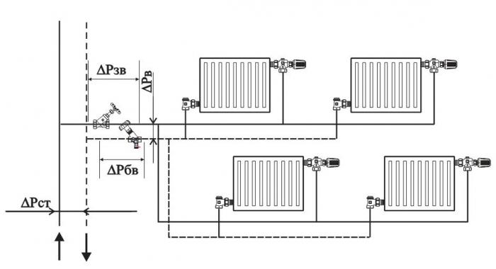
The heating system is understood as the interrelationship between a set of devices: pipelines, pumps, shut-off and regulating equipment, control and automation means for transferring heat from the source directly to the room.
Types of heating boilers
Before making a hydraulic calculation of heating systems, it is necessary to select the correct boiler (heat source). There are the following types of boilers: electric, gas, solid fuel, combined and others. The choice in most cases depends on the fuel prevailing in the area of residence. 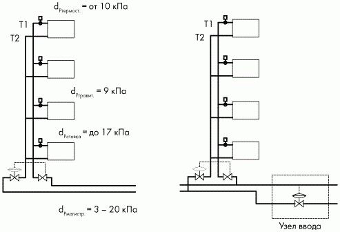
Electric boiler
Due to problems with power connections and a fairly high price for electricity this equipment has not reached its wide distribution.
Boiler gas
To install such a boiler, previously required a special separate room (boiler room). At present, this applies only to equipment with open camera combustion. A similar option is most common in places with gasification.
Solid fuel boiler
With relative availability of fuel, this equipment is not very popular. There are some inconveniences when using it. During the day, it is necessary to produce several times a furnace. In addition, the heat transfer regime has a cyclic character. The use of these boilers is facilitated (reducing the number of furnaces) by using a thermal cylinder or a fuel with a high combustion temperature, due to which the burning time is increased due to the controlled air supply. This can also be done by means of water heat accumulators, to which central heating is connected.
Required parameters for power calculation
- Wd is the specific power of the heat source (boiler) per building area of 10 m 2, taking into account the climatic conditions of the region.
- S is the area of the heated room.
Also, there are generally accepted values of specific power, which depend on the climatic zone:
- W ud = 0.7-0.9 for the Southern region.
- W ud = 1.2-1.5 for the Central District.
- W ud = 1,5-2,0 - for the Northern region.
Formula for boiler power
Before proceeding to such a crucial event as the hydraulic calculation of heating systems, you need to determine the power of the heat source by the following formula:
W cat = S × W ud / 10.
For convenience of calculation, we take the average value of Wd per 1 kW, so we get that 10 kW should account for 100 m 2 of heated area. As a result, the installation schemes of the heating system will depend on the area of the house.
In other cases, forced circulation of the coolant is used by means of circulation pumps.
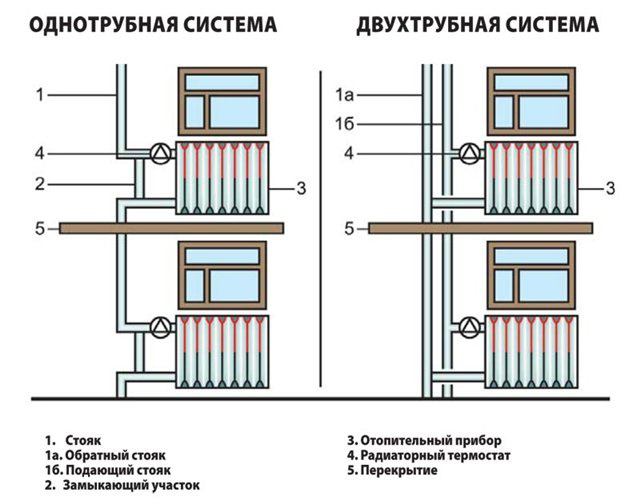
Two-pipe system
This is a classic version of the heating system, which has proven itself in the best way for a long time of operation. Hydraulic calculation will be considered below. Why is it called that? The thing is that the basis of engineering design was the installation of several pipelines through the floors of the building. To one riser with hot water a heating device was connected over all the floors, and chilled water from the heating device flowed into the pipeline laid alongside. 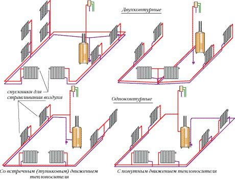
As a result, the coolant that had not yet cooled down from the first device came into the device, which was a floor below, and the circulating liquid had the same temperature as in the first one. Thus, the temperature of the coolant in the first and last pipelines was identical - this means that heat transfer was the same.
Two-pipe heating system - advantages
Central heating in a private house with a two-pipe system has the following advantages:
Calculation and graphic activities
Performing a complex hydraulic calculation of heating systems, first of all, it is necessary to produce a number of preliminary activities:
For the design section, one is accepted that has a constant flow of coolant and the same cross section.
Example of hydraulic calculation of a heating system
On the calculated segment, the heat load is equal to the heat flux that must be transmitted on the supply line, and on the reverse side already transmitted the circulating liquid that passed through this section.
The flow rate of the coolant G i - j, kg / h is calculated by the following formula:
G i - j = 0.86 × Q i - j / (t 2 -t 0), where
G i - j is the amount of heat in the calculated interval i-j;
t 2 -t 0 are the calculated temperatures of hot and cold liquids, respectively.
How to choose the diameter of pipelines
To reduce the costs of overcoming the resistance during the movement of the circulating fluid, the diameters of the pipelines should be located within the minimum velocity of the coolant, which is required to remove air bubbles that contribute to the appearance of air plugs. To reduce them, the diameter of the pipelines is reduced to a minimum value, which does not lead to hydraulic noise in the valve and pipes of the system.
All production pipelines are divided into polymer and metal. The first are more durable, the latter - mechanically more durable. Which pipes to use in the heating system depends on its individual characteristics.
Hydraulic calculation of the heating system - program
Considering the amount of work to be done at the design stage, you can use specialized software. 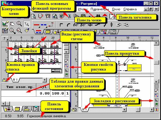
Using the initial data, the program performs automatic selection of pipelines of the required diameter, pre-adjusts the regulating and balancing and automatic regulators in the heating system. Also the program can independently estimate, what size heating devices are required.
The availability of a productive heat generator, quality pipes and modern radiators does not mean that heating will be effective. If the system is improperly designed, then situations are possible when a fully working boiler can not provide a comfortable temperature in all rooms. Either there is enough heat, but the energy costs are prohibitive. In order not to make irreparable mistakes, it is necessary to develop a project, an important part of which is the hydraulic calculation of the heating system. Perhaps the most difficult part.
Why calculate the hydraulics of the heating system
The essence of the problem
Modern heating installations are dynamic systems that, during operation, operate in different operating modes. The heating medium of water heating circulates under pressure, but this value is not constant. Losses occur on different sites because of constructive features systems (friction against the walls of pipes, resistance at fittings, etc.). We also manipulate the pressure ourselves, when we balance the distribution of heat through the rooms with the help of fittings. Manually or by means of system automation, the user controls the capacity of the heating device, changes the heating medium heating level. Again, the head of the network jumps, because the higher the temperature, the higher the pressure, and vice versa.
The pressure drop in a particular area leads to a decrease in its thermal performance. Quality heating should work in all conditions stably and economically, but for this it is necessary that to each radiator there should be exactly as much coolant as necessary for replenishing heat losses in the room and maintaining the set temperature.
Decision
One of the main tasks of the developer is to reduce possible head loss, which allows improving the regulation of individual sections and the system as a whole. There is a special term for "increasing the authority of the valve." It means that the local resistance, which the valve or valve has to the flow in the regulated branch, more favorably corresponds to the working pressure in the section. The more the volume of the coolant the concrete element controls, the more valuable it is.
Informative table as a result hydraulic calculationa
Also it is necessary to make a hydraulic linkage of the circulating rings. Competent use of balancing valves, valves, pressure regulators allows to avoid overheating of the rooms close to the boiler and the lack of heat in the remote (excess steam in the room - this is an over-expenditure of heat at the level of 5-10 percent). Restricting the flow in one branch, we increase it for others - we redistribute the coolant.
So, hydraulic calculation of heating helps the design engineer to solve the following tasks:
- calculate the throughput of pipelines and the drop in head on the main and secondary contours;
- select the cross-section of the pipes, if the flow rate of the coolant and the pressure in the system are already set;
- calculate the optimal ways of balancing the branches of the system;
- determine the necessary power of the circulation pump.
Stages of carrying out hydraulic calculation of heating
Collection and systematization of source data
Before starting the calculations, the developer studies the thermal characteristics of the object and prepares, based on the TK, suitable option heating systems. Perform the following activities:
- A thermal calculation is made, as a result of which information on necessary quantity heat for each room.
- Choose a heat generator and heaters.
- Decide on the methods of piping and the features of balancing the system.
- Choose the type of pipe and the specification of the control valve.
- Make up the axonometric wiring diagrams and detailed plans of the premises with indication of the basic initial data (coolant flow, battery power, arrangement of equipment, etc.). Nodal points, the main contour and individual sections are marked, the length of the rings is denoted.
Selecting a method
There are several ways to perform a hydraulics calculation heating system (as a rule, they are all performed using special software):
- addition of conductivity and resistance;
- by specific pressure loss;
- along the length of pipelines;
- comparison of dynamic pressures;
- by volume of the transported coolant.
The specific method is used depending on whether the temperature differences in the system are dynamic or stable. Also, the heating configuration is taken into account: some calculation methods are only suitable for single-pipe circuits wiring, others - are universal. Most often, the hydraulic calculation of the heating system pipelines is used for pressure losses.
Pipe cross-section calculation
Choosing the optimal pipe size is one of the most effective methods of controlling the performance of a heating system. Thus, the use of pipes with an overstated section entails:
- growth of capital expenditures;
- decrease in working pressure;
- a critical decrease in the rate of transfer of the coolant with a high probability of ejection;
- the appearance of a significant thermal inertia of heating.
Reducing the diameter of pipelines can reduce both capital and operating costs, but leads to an increase in the flow rate. At the indices from 0,6 m / s in the system there are noises, therefore optimal for residential premises is the speed of transportation of the coolant in the range of 0.3-0.7 meters per second.
To calculate the appropriate internal diameter of pipelines, the following data is used:
- The difference between the flow and return temperatures (for two-pipe circuits it is usually assumed to be 20 degrees).
- The coolant flow rate is indicated in the tables with the letter "G". In real calculations and in examples of hydraulic calculation of heating systems, this quantity, as a rule, is already preset.
- The rate of movement of water / antifreeze - is indicated by the letter "v"
- Density of coolant.
- The volume of heat flow is indicated by the letter "Q".
- Features of the site (length, number of sections in radiators, etc.).
Determination of pressure losses in the system and its individual sections
At each site, the overall pressure drop is due to two main factors:
- Resistance to friction, which arises from the roughness and roughness of the inner walls of the pipes.
- Local resistance, which has a pumping working environment connecting fittings, shut-off and control valves, rotations and branching, narrowing / expansion of pipelines. Also, the braking effect is created by heat exchangers of heating appliances and heat generators.
The level of pressure loss in the ring due to frictional resistance depends on:
- flow rate;
- coefficient of roughness of pipeline material;
- the length of the branch;
- diameter and shape of the internal section of the pipes;
- viscosity and density of the coolant.
The nature of local resistance is affected by:
- rate of fluid transfer;
- coefficients of local resistance (data for various nodes and devices are tabulated).
Accurate calculations are made according to generally available formulas, the results of resistances in individual sections are summarized, and the engineer is able to calculate the required capacity of pumping equipment.

Such schemes are generated by programs for hydraulic calculations
Development of coordination of circulation rings
The final stage of hydraulic calculation of the heating system. Analyzing the initial data obtained at preliminary stages (resistance, necessary heat loads, characteristics of the valve), the designer should equalize the pressure losses in the network. That is, ideally, the pressure loss in all rings of the system should be the same. To balance the head and redistribute the flow of coolant, manual valves or automatic valves are used, which are responsible for individual branches or installed on each heater. It is based on the results of hydraulic calculation, the preliminary adjustment of the control valves is performed.
Video: practical lesson of hydraulic calculation of heating system
Heating based on circulation hot water - the most common variant of the arrangement of a private house. For the competent development of the system, it is necessary to have preliminary analysis results, the so-called hydraulic calculation of the heating system, which links the pressures on all sections of the network with pipe diameters. The method of its implementation will be discussed in the article presented.
The determining factor in the technological development of heating systems has become the usual energy saving. The desire to save money makes it necessary to carefully approach the design, selection of materials, methods of installation and operation of heating for housing.
Therefore, if you decide to create a unique and primarily economical heating system for your apartment or house, then we recommend a spoiler.
The essence of the hydraulic calculation is that the flow rate of the heat carrier is not predetermined with a significant approximation to the actual parameters, but is determined by linking the pipeline diameters to the pressure parameters in all rings of the system
Before giving a definition of the hydraulic calculation of the system, it is necessary to clearly and clearly understand that individual system heating of the apartment and the house is relatively conditionally higher relative to central system heating a large building. The personal heating system is based on a fundamentally different approach to the concepts of heat and energy.

This type of radiator was installed in most panel houses in the post-Soviet space. Savings on materials and lack of design ideas "on face"
It is sufficient to make a trivial comparison of these systems with respect to the following parameters.
- The central heating system (boiler-house-apartment) is based on standard types of energy carrier - coal, gas. In an autonomous system, it is possible to use practically any substance that has a high specific heat of combustion, or a combination of several liquid, solid, granular materials.
- DSP is built on conventional elements: metal pipes, "clumsy" batteries, stop valves. The individual heating system allows you to combine a variety of elements: multi-section radiators with good heat dissipation, high-tech thermostats, PVC and copper pipelines, taps, plugs, fittings and of course own more economical boilers, circulating pumps.
- If we go into the apartment of a typical panel house built 20-40 years ago, we see that the heating system is reduced to the presence of a 7-cell battery under the window in each apartment room plus a vertical pipe through the entire house (riser), through which you can "communicate" with neighbors above / below. Whether it's an autonomous heating system (ASO) - allows you to build a system of any complexity, taking into account the individual wishes of the tenants of the apartment.
- Unlike DSP, a separate heating system takes into account a fairly impressive list of parameters that affect transmission, energy consumption and heat loss. The temperature regime of the environment, the required temperature range in the rooms, the area and volume of the room, the number of windows and doors, the purpose of the premises, etc.
Thus, the hydraulic calculation of the heating system (GRS) is a conditional set of calculated characteristics of the heating system, which provides comprehensive information on such parameters as the diameter of the pipes, the number of radiators and valves.

Another type of heating radiator for DSP. This is a more versatile product that can have any number of edges. So you can increase or decrease the heat exchange area
GRS allows you to select the water-ring pump (boiler) for transporting hot water to the final elements of the heating system (radiators) and, ultimately, to have the most balanced system, which directly affects the financial investments in the heating of the home.
Sequence of calculation steps
Speaking about the calculation of the heating system, we note that this procedure is the most ambiguous and important in terms of design. Before making a calculation, you need to make a preliminary analysis of the future system, for example:
- to establish a heat balance in all and specifically each apartment room;
- select and install radiators, heat exchange surfaces, heat-dissipating panels;
- select thermoregulators, valves and pressure regulators;
- identify general scheme transportation of coolant (complete and small circuit, single or double pipe trunk).
In addition, it is necessary to determine the parts of the system with the maximum and minimum consumption of the heat carrier. As a result of the hydraulic calculation, we obtain several important characteristics hydraulic system, which give answers to the following questions:
- what should be the power of the heating source;
- what is the flow rate and velocity of the coolant;
- what is the diameter of the main pipeline of the heat pipeline?
- what possible losses of heat and the mass of the coolant itself.
Another important aspect of hydraulic calculation is the procedure of balancing (linking) all parts (branches) of the system during extreme thermal regimes with the help of regulating devices.

There are several main types of heating products: cast iron and aluminum multi-section, steel panel, bimetal radiators and covectors. But the most common are aluminum multi-section radiators
The design zone of the pipeline main line is a section with a constant diameter of the highway itself, as well as an unchanged flow of hot water, which is determined by the formula of the room's heat balance. The calculation of calculation zones starts from a pump or heat source.
The initial conditions of the example
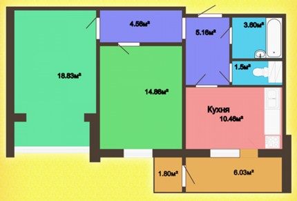
For a more specific explanation of all the details of hydraulic miscalculation, let's take a concrete example of an ordinary housing space. We have a classic 2-room apartment of a panel house with a total area of 65.54 m 2, which includes two rooms, a kitchen, separate toilet and bathroom, a double corridor, a balcony.
After commissioning received the following information regarding the readiness of the apartment. The apartment described includes walls treated with putty and primer from monolithic iron-concrete structures, windows from the profile with two chamber panes, tyroso-pressed interior doors, ceramic tile on the floor of the bathroom.
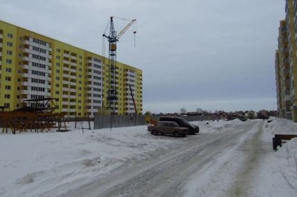
Typical panel 9-storey house on four entrances. There are 3 apartments on each floor: one 2-room and two 3-rooms. The apartment is located on the fifth floor
In addition, the presented housing is already equipped with copper wiring, valves and a separate flap, gas stove, bath, washbasin, toilet, towel, sink. And most importantly, in residential rooms, bathroom and kitchen, there are already aluminum radiators. The question of pipes and the boiler remains open.
How data is collected
Hydraulic calculation of the system is mostly based on calculations related to the calculation of heating by the area of the room. Therefore, you need to have the following information:
- the area of each individual room;
- dimensions of window and door connectors (internal doors for heat loss practically do not influence);
- climatic conditions, peculiarities of the region.
The area of the common room is 18.83 m 2, the bedroom is 14.86 m 2, the kitchen is 10.46 m 2, the balcony is 7.83 m 2 (the amount), the corridor is 9.72 m 2 (the amount), the bathroom - 3.60 m 2, toilet - 1.5 m 2. Entrance doors - 2,20 m 2, window showcase of the common room - 8,1 m 2, bedroom window - 1,96 m 2, kitchen window - 1,96 m 2.
The height of the walls of the apartment is 2 meters 70 cm. The external walls are made of concrete of class B7 plus internal plaster, 300 mm thick. Internal walls and partitions - load-bearing 120 mm, ordinary - 80 mm. The floor and the ceiling of concrete slabs of class B15, respectively, a thickness of 200 mm.
The layout of this apartment provides the opportunity to create a single heating line passing through the kitchen, bedroom and common room, which will provide an average temperature of 20-22⁰C in the premises
What about the environment? The apartment is located in a house that is located in the middle of a small town micro district. The city is located in a certain lowland, the height above sea level is 130-150 meters. The climate is temperate continental with cool winters and quite warm summers.
The average annual temperature, + 7,6 ° C. The average temperature in January is -6.6 ° C, in July - + 18.7 ° C. The wind is 3.5 m / s, the average air humidity is 74%, the amount of precipitation is 569 mm. Analyzing the climatic conditions of the region, it should be noted that we are dealing with a wide spread of temperatures, which in turn affects the special requirement for the regulation of the heating system of the apartment.
Heat Generator Power
One of the main components of the heating system is a boiler: electric, gas, combined - at this stage it does not matter. Since the main characteristic of it is power, that is, the amount of energy per unit of time that will be spent on heating. The power of the boiler itself is determined by the following formula:
- W = = (S * W *) / 10
where Sco is the sum of the areas of all rooms that require heating, Wudel is the specific power taking into account the climatic conditions of the location (that's why it was necessary to know the climate of the region).
What is typical, for different climatic zones we have the following data:
- for northern areas - 1,5 - 2 kW / m 2;
- for the central areas - 1 - 1.5 kW / m 2;
- for the southern regions - 0,6 - 1 kW / m 2.
These figures are quite arbitrary, but nevertheless give an explicit numerical answer regarding the influence of the environment on the apartment's heating system.

This map shows climatic zones with different temperature regimes. From the location of housing relative to the zone and depends on how much you need to spend on heating a meter square kWh of energy
The amount of the area of the apartment that needs to be heated is equal to the total area of the apartment and is equal to 65.54-1.80-6.03 = 57.71 m2 (minus the balcony). The specific boiler output for the central region with a cold winter is 1.4 kW / m2. Thus, in our example, the design capacity of the heating boiler is equivalent to 8.08 kW.
Dynamic parameters of the coolant
We pass to the next stage of calculations - the analysis of coolant consumption. In most cases, the heating system of the apartment is different from other systems - this is related to the number of heating panels and the length of the pipeline. Pressure is used as an additional "driving force" of the flow vertically through the system.
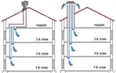
In private single- and multi-storey buildings, old panel apartment buildings heating systems with high pressure, which allows you to transport the heat-transfer agent to all sections of the branched, multi-ring heating system and raise the water to the full height (up to the 14th floor) of the building.
On the contrary, an ordinary 2- or 3- bedroom apartment with autonomous heating It does not have such a variety of rings and branches of the system, it includes no more than three contours. This means that transportation of the coolant takes place through the natural process of water flow. But it is also possible to use circulating household electric pumps, heating is provided by a gas / electric boiler.
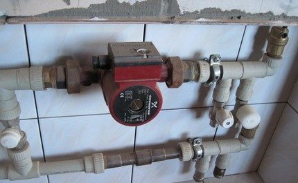
We recommend the use of a circulation pump for heating the premises of more than 100 m 2. The pump can be installed both before and after the boiler, but usually it is put on a "return" - less carrier temperature, less air pollution, longer pump life
Specialists in the design and installation of heating systems determine two basic approaches in terms of calculating the volume of the coolant.
- According to the actual capacity of the system. Summarizes all without exception the volume of the cavities where the flow of hot water will flow: the sum of individual sections of pipes, sections of radiators, etc. But this is a rather laborious option.
- By the power of the boiler. Here the opinions of the experts differed very strongly, some say 10, the other 15 liters per unit of boiler power.
From a pragmatic point of view, it is necessary to take into account the fact that probably the heating system will not only serve hot water for the room, but also heat the water for the bath / shower, washbasin, sink and dryer (and maybe for a whirlpool or jacuzzi). This option is simpler.
The calculated velocity of the coolant in the system is precisely the parameter that allows you to select a certain pipe diameter for the heating system. It is calculated by the following formula:
V = (0.86 * W * k) / t-to
where W is the boiler output, t is the supply water temperature, to is the water temperature in the return circuit, k is the boiler efficiency (0.95 for the gas boiler). (0.86 * 8080 * 0.95) / 80-60 = 6601.36 / 20 = 330kg / h. Thus, 330 kilograms of coolant (liters of water) are moved in one hour in the system, and the capacity of the system is about 110 liters.
Determining the diameter of the pipes
For the final determination of the diameter and thickness of the heating pipes, it remains to discuss the issue of heat losses.

The maximum amount of heat leaves the room through the walls - up to 40%, through the windows - 15%, the floor - 10%, everything else through the ceiling / roof. The apartment is characterized by losses mainly through windows and balcony modules
There are several types of heat loss in heated rooms.
- Loss of flow pressure in the pipe. This parameter is directly proportional to the product of the specific frictional loss inside the pipe (provided by the manufacturer) by the total pipe length. But given the current task, such losses can be ignored.
- Loss of pressure on local pipe resistance - loss of heat at fittings and inside equipment. But given the conditions of the task, a small number of fitting bends and the number of radiators, such losses can be neglected.
- There is another type of heat loss, but it is more associated with the location of the relative relative building. For a regular apartment, which is located in the middle of the house and is adjacent to the left / right / top / bottom with other apartments, the heat losses through the side walls, ceiling and floor are almost equal to "0".
In the calculation you can only take the losses through the front part of the apartment - the balcony and the central window of the common room. But this issue is closed by adding 2-3 sections to each of the radiators.
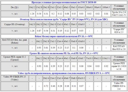
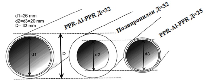
As can be seen from the table, the diameter of the metal pipe should be 16-18 mm with a thickness of 1.5-2 mm or 20-25 mm plastic PVC pipes with a wall thickness of 3-4 mm
Analyzing the above information, it is worth noting that for the calculated speed of hot water in the heating system, the tabular rate of movement of water particles relative to the pipe wall in a horizontal position of 0.3-0.7 m / s is known.
To help the master present the so-called check-list of calculations for a typical hydraulic calculation of the heating system:
- data collection and calculation of boiler power;
- volume and velocity of the coolant;
- loss of heat and pipe diameter.
Sometimes, when miscalculating, you can get a sufficiently large diameter pipe, which would block the calculated volume of the coolant. This problem can be solved by increasing the capacity of the boiler or by adding an additional expansion tank.
Video instructions and reviews
In the video presented, all the basics and subtle moments of the design and hydraulic calculations of heating systems are described on the examples:
The following video demonstrates the features, advantages and disadvantages of natural and forced systems circulation of heating medium for heating systems:
Summing up the calculation of the hydraulic calculation, as a result, received specific physical characteristics of the future heating system. Naturally, this is a simplified calculation scheme that gives approximate data on the hydraulic calculation for a typical 2-room apartment heating system.
Perform a hydraulic calculation of the heating system - this means choosing the diameters of individual sections of the network (taking into account the available circulating pressure) so that the calculated flow of the coolant passes through them. The calculation is carried out by selecting the diameter according to the available pipe grade.
For buildings with a small number of storeys, the most commonly used is a two-pipe heating system, for a high-rise one-pipe system. To calculate such a system, the following initial data should be available:
1. The temperature drop of the heat carrier common to the system (i.e., the difference between the water temperature in the supply and return lines).
2. The amount of heat that must be supplied to each room to provide the required air parameters.
3. Axonometric diagram of the heating system with heating devices and control valves applied to it.
Sequence of performance of hydraulic calculation
1. The main circulating ring of the heating system is selected (most disadvantageously located hydraulically). In dead-end two-pipe systems this ring passes through the lower device of the most remote and loaded riser, into single-tube ones - through the most remote and loaded riser.
For example, in a two-pipe heating system with an overhead wiring, the main circulation ring will pass from the heat point through the main riser that feeds the main, through the outermost riser, the lower floor heater, the return line to the heat point.
In systems with a co-moving water movement, the main one is the ring passing through the middle most loaded riser.
2. The main circulation ring is divided into sections (the section is characterized by a constant flow of water and the same diameter). The diagram shows the number of sections, their lengths and thermal loads. The thermal load of the main sections is determined by the summation of the thermal loads served by these sections. To select the pipe diameter, two values are used:
a) set water flow rate;
b) approximate specific losses of frictional pressure in the design circulating ring R wed .
For calculation R cp it is necessary to know the length of the main circulation ring and the design circulation pressure.
3. The calculated circulating pressure is determined by formula
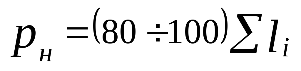
where  - pressure created by the pump, Pa. The practice of designing a heating system has shown that it is most appropriate to take the pump pressure equal to
 ,
(5.2)
,
(5.2)
where  - the sum of the lengths of the sections of the main circulation ring;
 - the natural pressure produced by cooling the water in the instruments, Pa, can be defined as
 ,
(5.3)
,
(5.3)
where  - distance from the center of the pump (elevator) to the center of the lower floor device, m.
Coefficient value It can be determined from Table 5.1.
Table 5.1 - Value depending on the design water temperature in the heating system
|
( |
|
 ), 0 C
 , kg / (m 3 K)
 - the natural pressure resulting from the cooling of water in the pipelines.
In pumping systems with a lower wiring size can be neglected.
Specific friction pressure losses are determined
 ,
(5.4)
,
(5.4)
where k = 0.65 determines the fraction of pressure loss due to friction.
5. The water flow at the site is determined by the formula
 (5.5)
(5.5)
(t r - t 0) is the temperature difference of the coolant.
6. In terms of  and
and  the standard sizes of pipes are selected.
6. For the selected pipeline diameters and design water flow rates, the velocity of the coolant v and the actual specific frictional pressure loss is set R f .
When selecting diameters in areas with low flow rates, there may be large discrepancies between and  . Low loss on these sites are compensated by overestimation of the values at other sites.
7. Determine the pressure loss for friction at the calculated site, Pa:
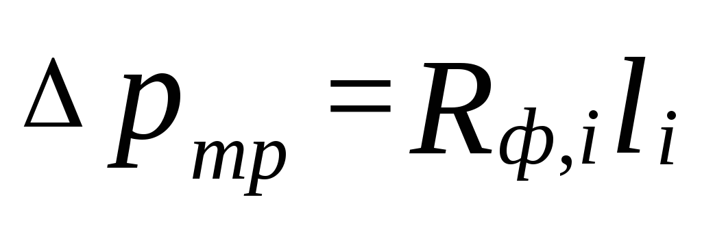 .
(5.6)
.
(5.6)
The results of the calculation are recorded in Table 5.2.
8. Pressure losses in local resistances are determined using either the formula:
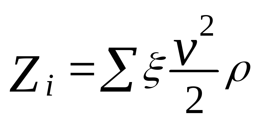 ,
(5.7)
,
(5.7)
where  - the sum of the coefficients of local resistances at the calculated site.
Value ξ on each site is reduced to tab. 5.3.
Table 5.3 - Coefficients of local resistances
9. Determine the total pressure loss in each section
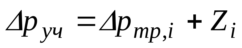 .
(5.8)
.
(5.8)
10. Determine the total loss of frictional pressure and local resistances in the main circulation ring
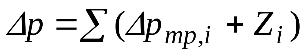 .
(5.9)
.
(5.9)
11. Compare Δp from Δp r . The total pressure losses along the ring should be less than the value Δp r on
The stock of available pressure is necessary for the hydraulic resistance not calculated in the calculation.
If the conditions are not met, then it is necessary to change the diameters of the pipes in some sections of the ring.
12. After calculating the main circulating ring, the remaining rings are tied together. In each new ring, only additional non-common areas are calculated, in parallel connected to the sections of the main ring.
The discrepancy in pressure losses in parallel connected areas is allowed up to 15% in case of dead-end water movement and up to 5% - at a passing one.
Table 5.2 - Results of hydraulic calculation for the heating system
|
In the pipeline diagram |
By prior calculation |
Upon final settlement |
||||||||||||||
|
Site number | , W
Coolant flow rate G, kg / h |
Length of the plot l, m |
Diameter d, mm |
Speed v, m / s |
Specific friction pressure loss R, Pa / m |
Loss of pressure on friction Δp tr , Pa |
The sum of the coefficients of local resistances ∑ξ |
Loss of pressure in local resistances Z |
d, mm |
v, m / s |
R, Pa / m |
Δp tr , Pa |
Z, Pa |
Rl+ Z, Pa |
||

What is the hydraulic calculation of the heating system? What quantities need to be counted? Finally, the main thing: how to calculate them, not having exact values of hydraulic resistance of all sections, heating devices and elements of the stop valves? Let's understand.
What we expect
For any heating system, the most important parameter is its heat output.
It is determined by:
- The temperature of the coolant.
- Thermal capacity of heating appliances.
Note: in the documentation, the last parameter is indicated for a fixed temperature delta between the coolant temperature and air in a heated room of 70 ° C.
Reducing the delta of temperatures by half will result in a twofold decrease in thermal power.
Methods for calculating the thermal power, we still leave behind the scenes: they are devoted enough thematic materials.
However, in order to ensure the transfer of heat from the route or boiler to the radiators, two more parameters are important:
- The internal section of the pipeline, tied to its diameter.
- The flow rate in this pipeline.
In an autonomous heating system with forced circulation it is important to know a couple more values:
- Hydraulic resistance of the circuit. Calculation of the hydraulic resistance of the heating system will determine the requirements for the pressure created by the circulation pump.
- The flow of the heat carrier through the circuit, determined by the capacity at the corresponding head.
Problems
As they say in Odessa, "they are."
In order to calculate the total hydraulic resistance of the circuit, it is necessary to take into account:
- Resistance of straight pipe sections. It is determined by their material, internal diameter, flow velocity and degree of wall roughness.
- Resistance of each rotation and diameter transition.
- Resistance of each element of the stop valve.
- Resistance of all heaters.
- Resistance of the boiler heat exchanger.
Collecting all the necessary data will clearly become a problem even in the simplest scheme.
What to do?
Formulas
Fortunately, for an autonomous heating system, the hydraulic calculation of heating can be performed with acceptable accuracy and without deepening into the jungle.
Flow rate
On the lower side, it is limited by the growth of the temperature difference between the feed and the return flow, and at the same time the increased probability of ejection. A fast flow will force air from the jumpers to the automatic air vent; A slow one can not cope with this task.
On the other hand, too fast flow will inevitably generate hydraulic noise. Elements of stop valves and rotations of bottling will become a source of irritating hum.

For heating, the range of acceptable flow rate is taken from 0.6 to 1.5 m / s; while the calculation of other parameters is usually performed for a value of 1 m / s.
Diameter
It is easiest to select it with the known thermal power from the table.
| Inside diameter of pipe, mm | Heat flow, W at Dt = 20С | ||
| Speed 0,6 m / s | Speed 0,8 m / s | Speed 1 m / s | |
| 8 | 2453 | 3270 | 4088 |
| 10 | 3832 | 5109 | 6387 |
| 12 | 5518 | 7358 | 9197 |
| 15 | 8622 | 11496 | 14370 |
| 20 | 15328 | 20438 | 25547 |
| 25 | 23950 | 31934 | 39917 |
| 32 | 39240 | 52320 | 65401 |
| 40 | 61313 | 81751 | 102188 |
| 50 | 95802 | 127735 | 168669 |
Head
In a simplified version, it is calculated by the formula H = (R * I * Z) / 10000.
In it:
- H - the desired value of the pressure in meters.
- I - loss of pressure in the pipe, Pa / m. For a straight pipe section of the design diameter, it assumes a value in the range of 100-150.
- Z - additional compensation factor, which depends on the presence of additional equipment in the circuit.
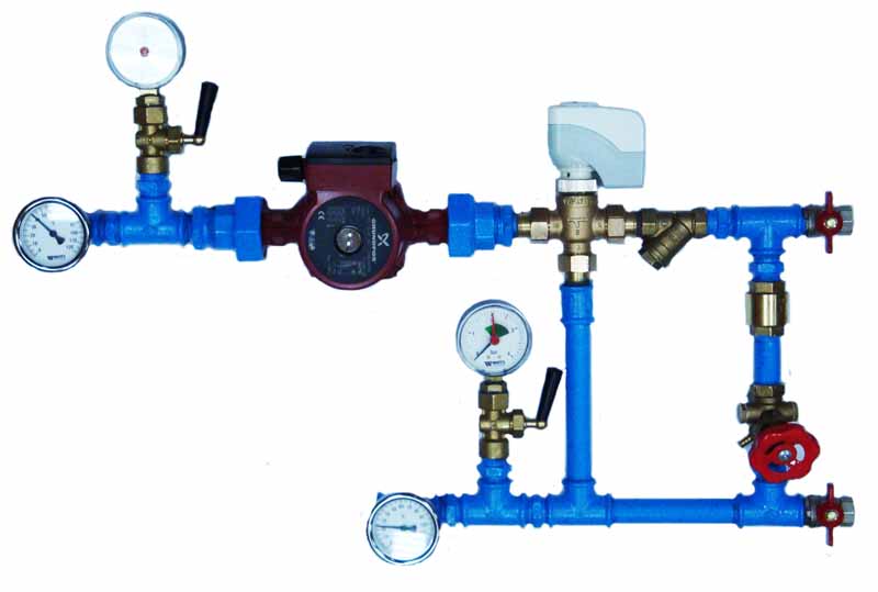
In the photo there is a mixing unit for heating.
If there are several elements in the system, the corresponding coefficients are multiplied. So, for a system with ball valves, and a thermostat controlling the flowability of filling, Z = 1.3 * 1.7 = 2.21.
Performance
The manual for calculating the pump's own performance is also not difficult.
Performance is calculated by the formula G = Q / (1,163 * Dt), in which:
- G - productivity in m3 / hour.
- Q is the thermal power of the circuit in kilowatts.
- Dt is the temperature difference between the supply and return pipelines.
Example
Let's give an example of the hydraulic calculation of a heating system for the following conditions:
- Delta temperatures between feeder and return pipeline is equal to the standard 20 degrees.
- Thermal power boiler - 16 kW.
- The total length of the single-tube Leningrad tower is 50 meters. The heating devices are connected in parallel to the filling. Thermostats that break the filling, and there are no secondary circuits with mixers.
So, let's get started.
The minimum internal diameter according to the above table is 20 millimeters with a flow velocity of at least 0.8 m / s.
It is useful: modern circulation pumps often have stepped or, more conveniently, smooth adjustment of productivity.
In the latter case, the price of the device is slightly higher.
The optimal head for our case will be (50 * 150 + 1.3) / 10000 = 0.975 m. Actually, in most cases the parameter does not need a calculation. Differential heating system apartment building, providing it with circulation - only 2 meters; this is the minimum value of the pressure of the absolute majority of pumps with a wet rotor.
The productivity is calculated as G = 16 / (1,163 * 20) = 0,69 m3 / hour.
Conclusion
We hope that the above calculations will help the reader to calculate the parameters of his own heating system without climbing into the jungle of complex formulas and reference data. As always, the attached video will offer additional information. Good luck!