How to properly connect the lamp through a one-button switch. How to connect the double switches correctly? Scheme and instruction
A single-pole switch is a switching device for the inclusion of only one group of light sources. Controlled by a button, fixed in two positions: on, off.
General information
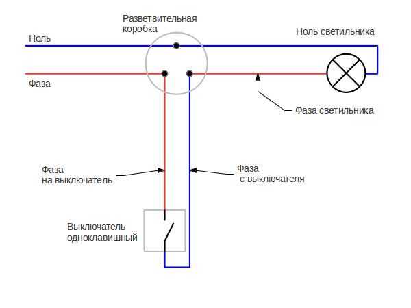
Its installation, connection and replacement will seem very simple, when you look at the diagram:
Wiring diagram of the switch in the distribution box
Indeed, a simpler electric circuit is hard to come up with. But, having no experience, you need to have this drawing before your eyes, and identify each wire with the lines depicted in the drawing, otherwise there will be an incident.
Calling an electrician from real life:
Hello, put the switch in the garage, turned on and there was no light anywhere!
The reason was that the phase closed to zero through the switch. The error was caused by the fact that in junction box there were line branches to outlets and other consumers.
Having single-color wiring is very easy to get confused. What looks simple and understandable on the diagram turns into a heap of wires sticking out of the box. Therefore, before making the connection or replacement, you need to carefully determine the functional identity of each wire. This article will tell you how to change the switch yourself.
To start:
- Do all work with the voltage off!
- Only the phase conductor connected to the internal contact of the lamp holder must be switched;
- The concealed installation switch will be conveniently connected if the length of the wires protruding from the junction box is equal to its diameter;
- Isolation is best removed with a stripper - a special tool.
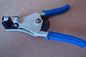
Stripper - tool for stripping
Replace obsolete or defective single-pole hidden switch
Depending on the design of the device, you need to get to the bolts that release the clamps. In old Soviet products, screws that fasten the front cover are loosened, and in newer ones, you need to click the button, using a flat screwdriver.
After loosening the clamping screws, carefully remove the switch from the back box. Remove the bolts and remove the wires and terminals. At this stage, difficulties may occur due to "sour" bolted joints - they can rust or become covered with oxides of copper, aluminum.

In this case, you need to put the core of the switch back into place, take a good stop and try, tightening the screwdriver tightly, unscrew the unbreakable connection. If you press down with a little effort, the tool will scroll, the edges will collapse, and there will be no way to unscrew the terminal.
If the efforts were not successful, you will have to bite off the wire cutters, hoping that you will have enough skill to remove the insulation and connect a new switch to the shortened cable. If the wire is broken off or becomes too short after biting it can be increased, using, depending on the number of expandable wires, one of the following terminals:
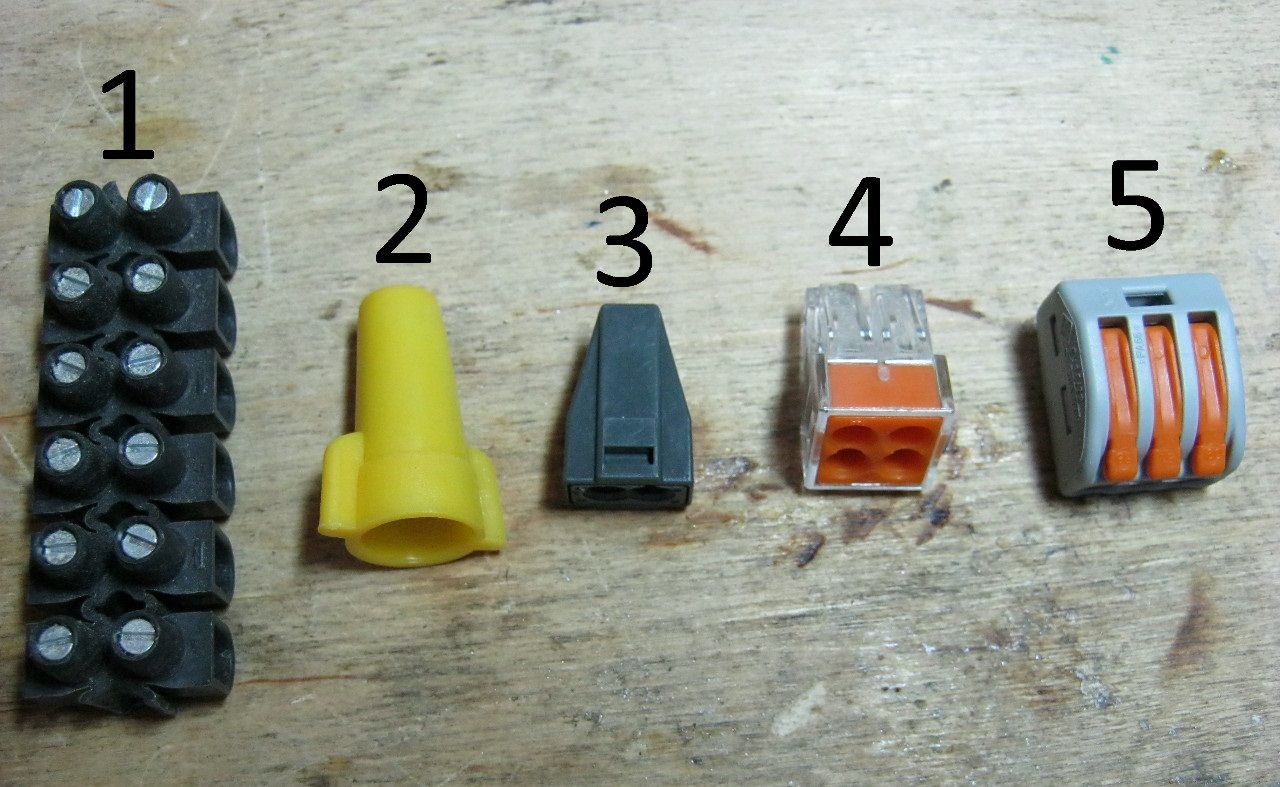
In the article about you can familiarize yourself with these connections
Insert the wires into the terminals of the new switch and firmly clamp.
Replacing the old jar
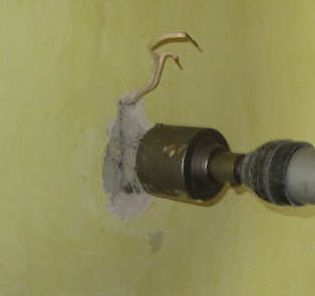
It may be that the previously used metal podrozetnik has come to full disrepair, and it must be replaced. In this case, the main warning is not to damage the wire!
With a chisel or a perforator, the assembly gypsum around the cylinder is hollowed until it is free. Carefully take it out, and the new wires are attached to the protruding wires, and fix it with gypsum or alabaster.
It is necessary to wait until it is completely solidified before proceeding with the installation - the mounting brackets will deform the box walls, which, when resting on a loose solution, will crush it, which will cause the switch to be squashed during operation.
While holding the switch in this position, the bolts should be clamped several turns each until they are completely locked. Click the button, apply voltage, check for light when it is turned on.
Replacement of the open installation switch with a single-pole hidden switch
There is a combination hidden wiring and an open, overhead switch. In this case: disconnect the cable, disassemble the device to be disconnected, remove it and various attachment devices. Mark the place of installation of the new switch taking into account the existing cable.
Practice shows that you need to move upwards so that the length of the wires is enough to connect. Very carefully, with only a hand tool, remove the plaster along the cable a dozen centimeters up, releasing it along this length from the wall and bending it horizontally, trying not to damage it.

crown for a jar
If the wall is concrete, then the groove for the installation is made with a perforator and a special drill bit, but you can do it with enough labor, manually, the main thing is that the special piece for reinforced concrete is fully enclosed and does not protrude above the surface.
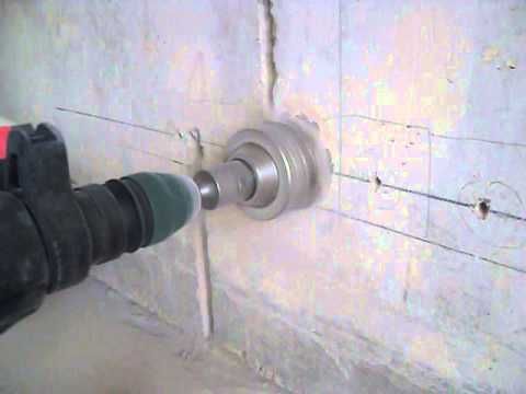
For brick masonry such a:

Then bend the cable back, break the hole under it in the junction box, pass and fix the jar, cover with the solution of the previously released part of the wiring. The next order of connection is the same as the one described above.
Replace the switch and part of the wires
If the option is to be replaced with hidden installation circuit breaker and wiring, the old wires from the junction box to the switch will be better to replace, because certainly the existing cable is not designed for hidden installation.
Let us assume that the junction box remains the same. In this case, disconnecting the old wires and unwinding twists, you need to mark them according to the connection points, so that you do not have to call a familiar electrician, as in the example described at the beginning of the article.
For laying new wiring in the wall, make a furrow with a perforator, chisel or special tool - fines cutter. Without its presence, in order to facilitate the task, first two diamond cuts make a diamond circle, and then the concrete between them is chipped.

It should be remembered that reinforced concrete panels in houses are considered to be bearing, and it is possible to make a ditch only to the depth of the reinforcement. Install the wiring, starting from above, with the help of self-locking clamps in the holes, then fasten with a quick-setting mortar.
According to the methods described above, it is necessary to fix the sub-socket and connect a single-key switch. Connecting the wires in the box will complete the installation process.
From this article you will learn how to install the light switch correctly. Switches are used to control electrical lighting sources in residential and commercial premises. In most cases, the switches are mounted on the wall. The location, the height at which they are installed, the shape of the switches vary from country to country. Switches are different types of: single or multi-key, for indoor or open air etc. Installing and connecting a circuit breaker is a simple task, provided that you understand the basic principles electrical networks and observe the safety precautions when conducting electrical work.
In this article, we will show you step by step how to install a switch. To do this you will need:
Instruments:
- voltage indicator;
- pliers;
- screwdriver;
- level;
- protective gloves and goggles.
Advice:
- before starting work, disconnect the power supply in your apartment;
- before touching the wires, use the voltage indicator on each wire to make sure that the power supply is off;
- if you are in doubt, if you do not want to risk, it's better to hire a professional electrician.
Preparatory work
The first thing you should do is turn off the power. Some people believe that it is enough to disconnect only the circuit on which the switch is to be installed, but we strongly recommend that you completely de-energize your apartment.
Using the voltage indicator on each wire, make sure that you can safely touch them. It is better to check several times before starting work.

The next step of the project is cleaning the jar (mounting box) from the paint, small pieces of plasterboard, dust and dirt. This operation is very important, especially if it is a newly renovated room or apartment in a new building. But even if you are replacing the old switch, it is better to assess the condition of the junket in advance to make sure that the new switch can be installed and aligned properly.

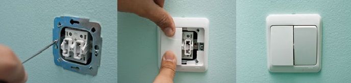
Preparation of the receptacle for installation of the switch.
After you have bought a new switch, you must disassemble it using a screwdriver or simply with your hands, depending on its type and manufacturer. Without this operation you can not do, since you will connect electric wires to the inside of the switch. It is necessary to remove the switch buttons and the frame.
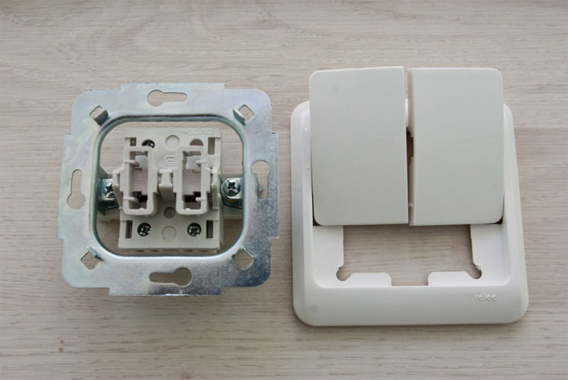
Disassembled switch.
Now you have to connect the wiring. Using pliers, cut off excess length of wires - they should protrude from the wall by about 15 cm. This length should be enough to connect the switch without any difficulties. Do not leave the wires too long, otherwise they will be difficult to place inside the juniper.
In the article we will talk about the ways of connecting one, two or more light bulbs in one and two-switch switches, we consider schemes that will simplify the course of work.
General scheme of electrification of premises
The general scheme of electrification of a room can be conditionally divided into two parts - feeding consumers and providing lighting.
In the first case, everything is simple - the wiring is thrown from the switchboard, (if necessary, it is divided), thanks to which branches are created, and brought to sockets through which consumers are connected to the power grid.
The sockets themselves are constantly energized after the connection.
In the case of the organization of lighting the room, it is not so simple, since it is necessary to create a branch, which provides the possibility of de-energizing the lighting elements - bulbs.
For this purpose, circuit breakers are provided in the circuit, the task of which is, if necessary, to interrupt and restore the voltage supply circuit to the consumer.

For the normal operation of lighting in the room and security, there are certain schemes for connecting lighting devices through switches to the mains.
Moreover, there are several versions of them, which makes it possible to organize the connection of bulbs according to the planned layout.
For example, with just one switch, you can control the lighting of several rooms, independently of each other.
Previously, used switches that crashed into the wiring. That is, from the switchboard, the wiring to the lamp cartridge was thrown directly, and then the phase conductor of the wire was cut at the right place, and a breaker was installed in this gap.
This method of lighting elements is now almost not used and the types of power connections for lamps are somewhat different, but the principle is the same.

General Provisions
The features of creating such branches largely depend on the number of lamps connected to them, as well as their control by means of a switch.
But in any case, the created branch includes:
- Switch (one-, two-, three-key);
- Lamps with cartridges;
- Junction box;
- Wires (two- and three-wire).
A little about the features of the interrupter.
Any switch has two outputs - input and output (the latter can be several).
In this case, they both belong to the same line, that is, if a phase is connected to the input terminal, it will be at the output.
By moving the key to a specific position, the terminals of these pins are connected or disconnected, thereby closing and opening the circuit.

Safety precautions.
Before describing the methods of connection, we immediately recall the safety precautions during the work.
To avoid electric shock, disconnect the mains and take measures to prevent accidental resumption of power until the end of work.
Restore its feeding should only after full laying and connection of all components of the branch, as well as ensuring reliable isolation of the places of connection of wires.
One lamp - one switch
The most simple circuit consists of a single lighting element and a one-button switch.
Theoretically, the connection does not differ from the one described above - the zero conductor goes directly from the distribution board to the consumer, but the breaker is inserted into the phase conductor. But almost everything looks a little more complicated.
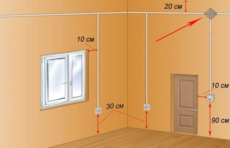
To connect this type, first determine the installation location of the junction box.
It should be installed as close as possible to the installation site of the circuit breaker, and ease of access to it should be avoided.
This directly determines the number of wires required to create a branch. The optimal location is under the ceiling above the switch.
- Determine the location of the lighting element - the lamp (for example - in the center of the ceiling);
- We choose the place of installation of the breaker (conditionally - below the junction box);
- In the junction box we start the wiring coming from the switchboard;
- On the ceiling we lay the wiring (on the shortest possible path) from the lamp holder and also put it into the box;
- It remains to install the wire from the switch to the junction box.

For simplicity, the wire going from the shield to the box will be designated as "input", and from the box to the consumer - "output".
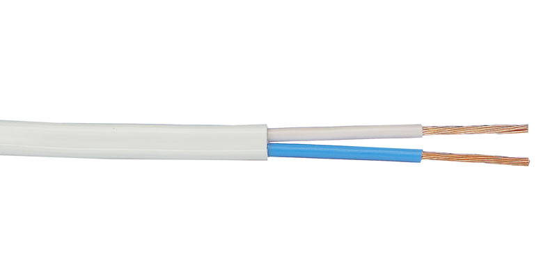
For a circuit with a single-key switch and a single lamp, two-wire wires are used.
After laying all the wiring (open or closed method), it remains only to connect everything correctly and for this it is important to determine which vein is phase and which is zero.
To find out this, you can use an indicator screwdriver, making an appropriate check on the terminals from the switchboard before turning off the power supply.
To make it clearer, let's look at how to connect everything correctly using a different color of the wire braid veins.
For example, to create a power branch of the lighting element, a wire with brown- and blue-colored veins was used.
When connecting the lead-in wire to the switchboard, the brown core was connected to the phase lead, and the blue wire to the neutral conductor.
Knowing this, it remains only to connect everything correctly in the junction box.
Since "zero" goes directly to the consumer, the blue (zero) core of the input is connected to the corresponding residential output.
It remains to switch on the circuit breaker. From him to the junction box, too, throw a two-wire wire, but in this case it is two parts of one line (phase).
Take the brown (phase) core of the input and connect it to any of the cores, for example, also from the brown, leading to the switch.
It remains only the blue core coming from the switch, connect with the brown residential outlet.
![]()
This we have discussed in detail how to connect one lamp to a single-key interrupter.
All the subsequent schemes are constructed according to the described principle, therefore we will only mention their key points.
Connection of a two-button switch
Next will be a circuit in which a two-key switch is activated.
A feature of its design is the presence of two output terminals, each of which can be connected to the input (phase) terminal independently of each other.
This allows you to create two separate branches from one input wire, for power management which has its own switch key.
Usually a two-key switch is used to power two lamps, but there are situations where you only need to power one lighting element, that is, create one branch.
In this case, the connection does not differ from the one described above. The only thing is to determine which key will be working and to connect to its output terminal a phase conductor.
With this connection, the second key will be disabled.

Now consider the features of connecting two light bulbs to such a breaker. That is, in fact, we create two branches from one phase vein.
The difference from the above scheme is that we will have two outputs from the box (each on its own lamp).
That is, the junction box must include 4 wires - lead-in, two outlets and a switch.
Another important point - from the breaker to the junction box will have to lay a three-wire wire.
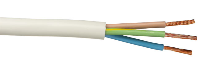
One of the cores will be connected to the input of the switch, and the other two to the output.
For example, the third color in the three-core cable will be green.
The connection is made like this:
- Zero wire (blue) from the input is connected with two output wires of the corresponding color (should be a twist consisting of three cores);
- The lead-in phase wire (brown) is connected with the same color, leading to the switch;
- The other two wires of the cable leading to the switch must be connected to the phase conductors of the terminals. That is, you need to connect the blue from the brown one branch, and the green one - from the brown of the other branch.
Kind time of the day, dear guests of the site "Notes electrician."
A small foreword.
Remember, a few days ago I installed the apartment? So yesterday I was called by the owner of this apartment with a request for help.
According to him, "the light" disappeared in the corridor. I told him on the phone I had to check the serviceability of the lighting lamp, but he told me that he checked the lamp and it is working. Then I decided to visit him and see why there was no lighting in the corridor. But I told him what was his, what he convincingly assured me of the opposite.
Beginning of work
Here is a similar scheme, only instead of one bulb, five are connected.
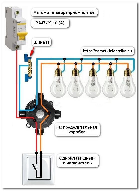
Attention!!! The switch should always break the phase, not the zero.
All this is necessary for our own sake. When replacing the lamp, it will be sufficient to disconnect the switch and there will be no voltage in the cartridge. Change yourself calmly. If you confuse, and switch the switch to zero, then when you replace the lamp, it will in any case remain energized. And this is very dangerous. Read my articles about and (example).
Looking for a malfunction
Let's return to the malfunction.
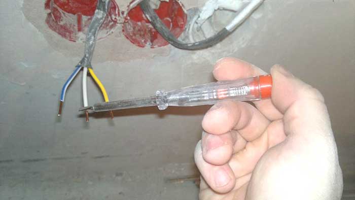
So, having unscrewed the bulb from the cartridge (E27) and turned on the switch, we check with the help of the coming phase (orange in the picture) from the switch to the lamp or not. In our case, the phase of the lamp does not come. This indicates the following faults. Either it is a faulty switch itself, or from the switch to the lamp is in the breakage (see circuit circuit breaker).
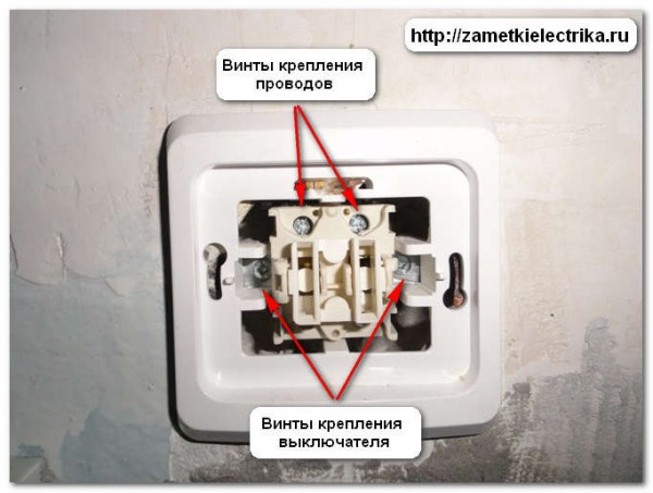
After removing the key, we will see the screws for securing the switch to the sub-socket and the screws for securing the wires to the switch. Here, we need to make sure that there is a phase on the conclusions.
For this we again apply, and we measure the incoming phase and the outgoing phase.
And here we were waiting for a "surprise".
The phase on the switch came, and from it did not leave any more. This indicates that the breaker itself is faulty. Therefore, it must be removed.
Turn off the voltage in the apartment with. By the way, this is the feature of this apartment. If you have in the apartment or are several lines (groups), respectively, turn off the machine of the line (group), where the work will be done.
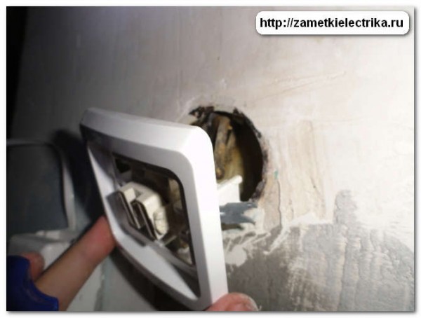
Then unscrew the screws fastening the switch and gently bend it. Please note that I have not twisted the screws for fixing the wires yet.
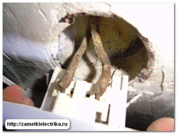
Old enough.
The reason for the missing wire is the weak pulling of the screws for fixing the wires.
Completion of work
The fault has been eliminated, the wire is inserted back into the terminal and the screws are tightened.
The switch is connected. It remains only to insert it in and tighten the screws of the switch fastening.
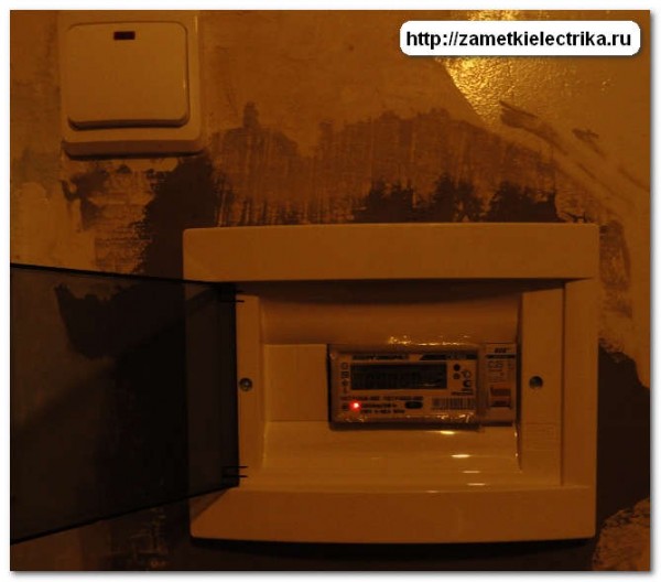
And now you can check the work done. We turn on the voltage on the switched off part of the circuit and check the operation of the single-key switch. Everything works fine.
- one of the simplest. Step by step I explain how to assemble the connection scheme. Look at the photos themselves - in total there are three connections in the switchbox. Who did that knows - it's just that if there's nothing in the box besides these wires on the lamp and the switch. But often it happens that in the switchbox there are wires not for one lamp, and even on the outlets can be immediately laid out, then when assembling the circuit you need special care and accuracy. What would be clear even to the most inexperienced teapots, I wrote a photo-instruction.P.S. Well, on this and finish the article, where I told you about the scheme of connecting a one-button switch and how to troubleshoot a wiring.
Wiring diagram of the circuit breaker.
If there is no possibility to watch video, practically the same thing was written below. circuit breaker connection. Before starting work, there are in view of electrical work, be sure to make sure that there is no dangerous voltage on the job site. Here I show how to assemble a circuit in a switch box, so there should be no voltage on the wires that are connected. We turn off the machine and check that the voltage is removed. Only after that we continue to work. When connection of a single-key switch In the switch box for the assembly of the circuit three wires must come: the first is the power wire, or the lead-in wire that goes to the machine or plugs with a voltage of 220 volts. The second wire is to the switch, the two-wire third is the wire to the lamp or lamp.Wiring diagram to the switch
By the way, many luminaires have a grounding clamp on the casing, so a three-wire wire-phase, zero and grounding is required. So, in the switch box comes three wires on two cores (the ground wire from the lamp does not count). Next, I'll call the veins wires - so right. After checking that the voltage on the wires there - remove the insulation in order to make twist. It is also suitable for this purpose and wago clamp, but I show on twist.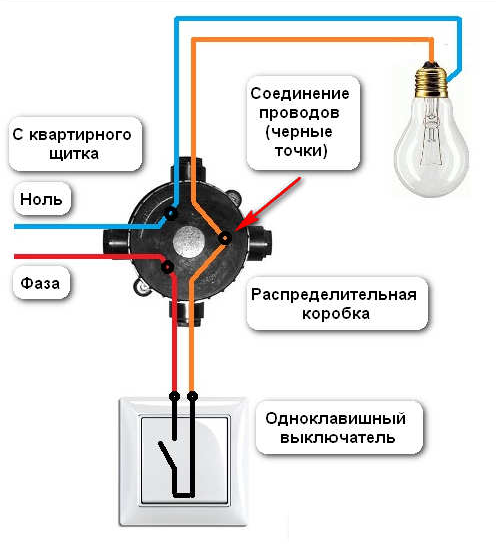 The circuit is assembled as follows: circuit diagram of the circuit breaker. The switch is connected to the phase wire break. Zero wire goes to the lamp directly, naturally through a junction box. Phase through the switch is done to ensure that afterwards, when servicing the luminaire, repair or replacement of the lamp does not get under tension. And simply it is more convenient - turned off the light and change the lamp or lamp lightly.
  So we find the phase power wire that comes to the switch box from the input and connect it to one of the wires going to the switch. I always use a white or red wire for this. With the switch, the phase is returned by another wire and connected to the wire going to the lamp. The remaining wire from the lamp in the switch box is connected to the neutral power wire. circuit breaker connection. I check the circuit as follows: visually I look in the switchbox - the phase came, went to the switch. With the switch came in the box - went to the lamp. With phase everything. Further. Zero came into the box - went directly to the lamp. All! The circuit is assembled and verified.
  Next, I twist tightly twisting the pliers and weld with my new welding torch. Then I put on the PVC pipe and fix it on the twists with electrical tape. I put the wires neatly into the junction box and close the lid. All! This is how it is going to connection diagram of a light switch with one key. In the next lesson, I'll show you how to put together a connection diagram two-key switch. More details on today's topic can be seen in the photos.

