How to connect a two-button light switch with your own hands. How to connect a double switch
Two-key switches are used when necessary to control two electric lighting devices simultaneously and from one point. They also adjust the brightness of the lighting. Simply put, connecting a light switch with two keys creates additional convenience for the user.
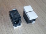
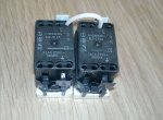
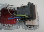
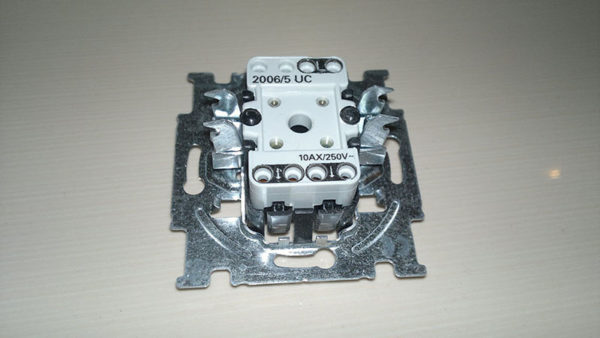
The internal arrangement of the two-phase circuit-breaker differs from the single-phase switch by the presence of two output terminals instead of one. More specifically, it consists of such elements:
- mechanism and decorative panel;
- one input terminal;
- two output terminals;
- two keys.
The terminals are special clamping mechanisms. To connect the wire, just clean it, insert it into the terminal block and clamp it with a screw. The input or common terminal is located separately and labeled as L.
On the opposite side there are two output terminals. They can be designated as L1, L2 or 1,2. Some models may have screw terminals instead of a terminal block. It is undesirable to use them, since the fastening can be gradually weakened and it will have to be squeezed.
The main difference of the switch with two keys from the one-button fellow is that it manages a pair of lighting devices
You need to install the device so that when you turn it on, press the upper half of the key. To determine the top and bottom of the element, you can use the indicator - a special screwdriver, which works on the closure. To do this, take a nail or a piece of wire and touch it to one contact, to another put an indicator, holding the thumb on top.
The device of the switch with two keys is slightly different from the one-key switch. The main components of the device: mechanism, keys and decorative body
If the light inside does not burn, then the breaker contacts are open. When the keys are on, it should be lit. It remains to mark the top of the element.
Step-by-step description of the work process
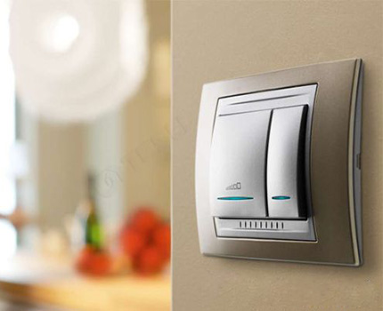
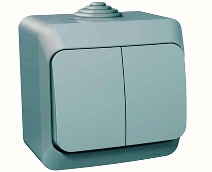
In addition to standard models, the switch of two keys can additionally be equipped with a backlight, an indicator. The backlight helps to identify it in the dark, and the glowing indicator will make it clear that electrical network is serviceable and is closed. They also produce models with impact-resistant and moisture-proof enclosures. They can be installed in the bath, bathroom or on the street.
There are also pass-through switches. They have the same structure, except for the additional terminal. Such devices are connected to one or a group of fixtures and allow you to control lighting from opposite ends of the room. For example, when entering the bedroom, you can turn on the light, and when you go to bed, turn it off near the bed.
Image Gallery

How to choose a location for installation
There are no standards for the placement of the device by law. Their installation implies convenient use for adults and children. And if before the usual practice was to place the device at a height of about 2 m, now the switch is often placed at the level of the lowered hand of an adult's hand. Thus, the element becomes available for almost all residents of the house.
Place the switch better so that it is accessible to everyone except the smallest ones
The only place where the switch placement can have any restrictions is a bathroom or a bath. Here you need to consider the placement of a washbasin and an open shower. When operating the device, it should not fall under the water drop.
Preparing for installation
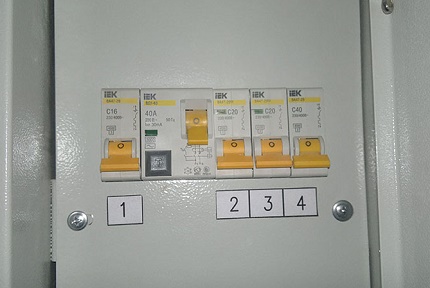
Whichever electrical installation work you have to do, the first thing to do is to de-energize the network. For a second you must not forget that electricity is dangerous. In addition to the current, illiterate wiring can cause electrical equipment damage or fire in the house.
Rules of conduct when working with electrical networks:
- be sure to de-energize the network;
- do not touch the connected devices with wet hands;
- do not use metal braces to secure the wiring;
- do not overload the electrical network;
- the damaged wire should be replaced with a new one, and not repaired;
- perform work only with a tool with insulated handles;
When working with electricity, you can not touch water pipes or gas pipes.
When starting an independent connection, you must:
- take steps to comply with safety regulations;
- familiarize with the laws of marking wires;
- check the network for compliance with the marking.
Any owner of the house to replace and connect the switch is unlikely to want to invite an electrician. In addition, to perform this task, there is no need for complex instruments and instruments. To install, you need:
- mounting knife;
- insulation tape;
- hammer and chisel;
- pliers;
- indicator screwdriver, as well as curly and straight.
If the installation has to be carried out in a new location and the house has buried wiring, a drill with a "crown" or a perforator may be useful.
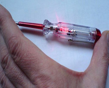
Without a screwdriver-indicator, not a single electrical installation work
Color marking of electrical wires
Without knowledge and observance of marking, it is absolutely impossible to proceed with installation. It is used to create safe conditions and reduce the time spent on the work.
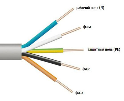
Correct labeling from the manufacturer will help to avoid problems with the identification of conductors
To form the correct connections, the following notation is used:
- zero - always and without exceptions blue;
- protection is also strictly one color - yellow-green;
- phase - predominantly brown or red.
These are just the basic combinations. In addition, to avoid confusion in the identification, alphanumeric marking is used.
If the work reveals the absence of visual signs, then it is necessary to mark the wiring by itself using a multi-colored shrink tube or color insulation.
How to independently identify the conductors
Blindly trust marking is not worth it. These designations have changed their standards more than once. Therefore, when proceeding to business, it is necessary to additionally check the nature of the conductors. To do this, use an indicator screwdriver and a multimeter.
If a single-phase electrical network without a grounding system is installed in the building, the indicator will determine the phase or zero. By turning off the electricity, the conductors are stripped off and retracted so that they do not touch each other. After turning on the power supply, a screwdriver is brought to the wires. The light in the indicator will flash, when touching the conductor of the phase, and from touching zero will not light up.
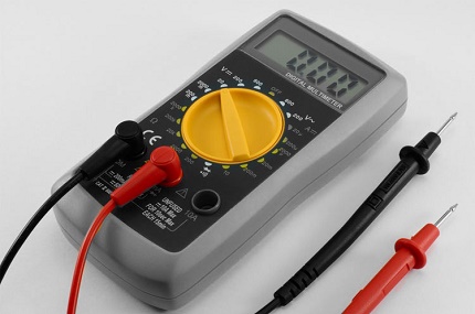
The multimeter is a multifunctional test and measurement device that performs the work of at least three control devices: voltmeter, ohmmeter and ammeter
To analyze the network, in which there is a third, protective conductor, use a multimeter. Setting the range for AC to a value above 220 volts, bring one tentacle to the phase, the other is fixed to any of the conductors. When in contact with a neutral wire, the device detects a voltage within 220 volts, with a protective one - a bit lower.
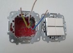
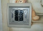
Dismantling of the old electrical switch
To have access to the fastening elements, you need to remove the keys and decorative panel. To do this, use a screwdriver or a thin knife to press the first key and gently pull it out. So do the second one. Next, remove the decorative cover. In some models they are unscrewed.
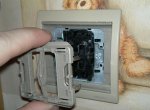
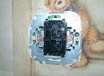
The basic rule of safety when working with electrical wiring and wiring devices is the disconnection of the mains voltage for the period of production
Then remove the mechanism itself - it can be fastened with clamping paws or screws. Unplug the conductors and, if necessary, dismantle the old junket.
Image Gallery
Installation of elements with closed and open wiring
The installation of switches in newly built dwellings is reduced to connecting the element to a previously conducted electrical network. In the old house, where the old wiring already requires replacement, you have to make new fines and lay the cable. And when the wiring is open, each cable is fed to the switch in the insulating corrugated tubes, cable channels.
From the way of laying wires in the house depends on the subsequent choice of the model of the switch, and the method of its installation. The device, which is suitable for open wiring, consists of a flat receptacle, an internal mechanism, an insulating decorative cover. The design does not hide in the deepening of the wall, but completely protrudes above the surface.
The arrangement of switches for open and closed wiring differs only in the shape of the juniper. In overlaid devices, it is a thick plate of dielectric material
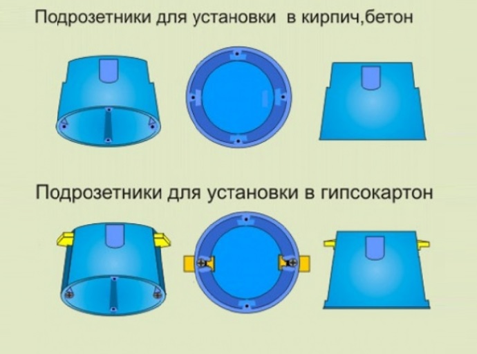
The installation begins with the installation of a podzetetnik - flat bottom. Implement it with the help of suitable fasteners. For different wall surfaces, screws or dowels, screws, screws can be used.
Next, after connecting the wires, fix the mechanism of the switch, put on the decorative insulating cover. In it, the manufacturer has already thought through the hole for the conductor. The cover itself is put on by hiding the mechanism, and fixed with the help of latches.
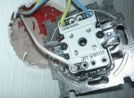
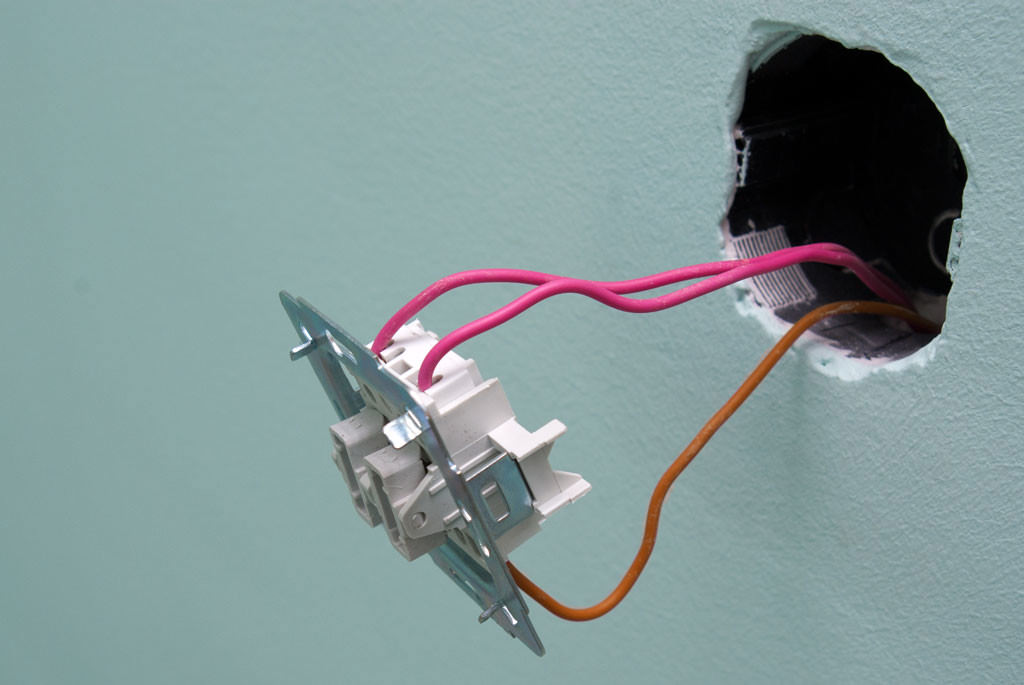
For the installation of a two-phase switch in premises with concealed wiring, use small pans (mounting boxes) in the form of a small bowl. A hole is cut in the wall or a small groove is made of a suitable size.
Reliably fix the mounting box in the wall helps clamping clamps: when tightening the screw they are slightly spread out and rest against the wall surface
During installation, ensure that the device is fixed smoothly, without distortion. Dipstick can be installed side by side - any required amount - and fixed using gypsum mixes. Then to meet the podrozetniku hollow out the depths, sufficient to lay the wire.
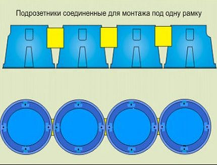
Dashboards have special mounts that help them to cling to the "neighbors"
How to connect electrical wires correctly
Places of joints are the weakest links in the electrical circuit. Not surprisingly, most of the problems occur there.
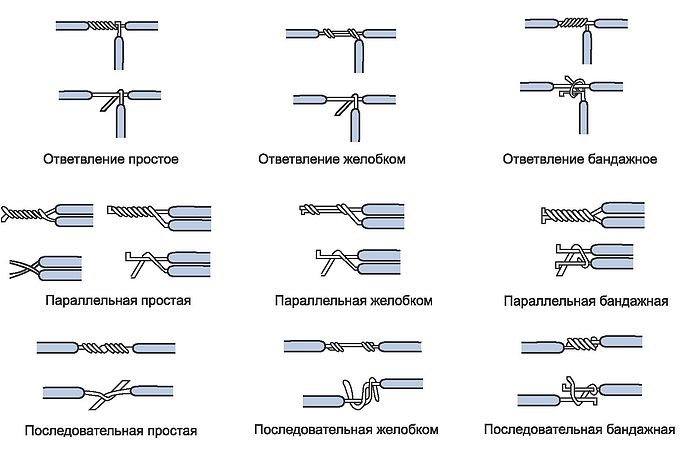
The easiest way to connect wires independently with twists with additional fixation of electrical tape is not reliable. In case of poor performance, this is the most common cause of a circuit break (+)
When connecting the switch, all connection methods are not necessary to consider, here are the most basic:
- Manual twisting is a very common method that requires subsequent isolation.
- Terminal block - widely used as a connecting link. It consists of copper clamps, clad in a plastic case.
- Soldering - though it helps to create a quality grip, but the laboriousness of the process does not contribute to its popularity.
It should be said about the shrink tube, which helps to isolate the connection points and even strengthens them a little.

Heat shrinkable tubing, when heated, tightens around the wire, creating a reliable protection
Connection scheme and step-by-step actions
With the old system of electricity supply, the power is supplied to the house from the electrical panel, via a two-wire cable. The ground loop is placed on the transformer to which the neutral conductor is connected. Despite its simplicity, this method has a significant drawback - a low level of security.
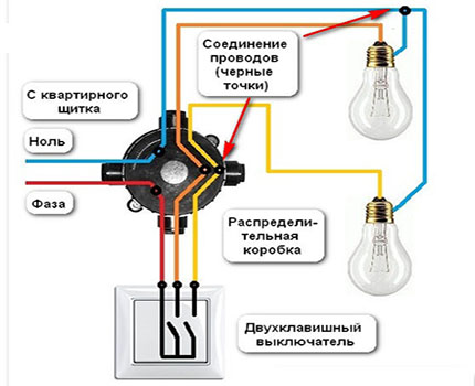
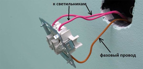
In the two-switch switch, the phase is connected with one wire, and each lamp to a separate terminal
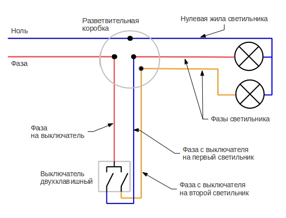
In the switch housing, one of the three-wire phase conductors is connected to the common terminal block (L). For this, the wire is wound into the terminal hole and tightened with a screw. Two other phase conductors are connected to separate contacts, and then lead to the junction box and connected to the phases of the luminaires.
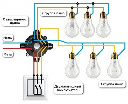
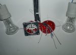
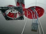
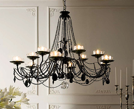
When connecting a multi-lamp chandelier to a two-button switch, the lamps are divided into two groups
The wiring connection must be carried out in a special box. She hides from the look of inaccurate weave and serves as an insulator. To connect the electrical wires correctly, proceed as follows:
- The conductors coming from the luminaires and the two-phase switch, as well as the power supply line, are put into the box, the insulation coating is removed from the 2-3 cm section.
- Connect the phases of the main supply cable and the switch.
- The incoming neutral wire is connected to the neutral wires of the luminaires.
- The phases that depart from the switch are connected in turn to the conductors of the phases coming from the lighting devices.
Only the phase wire is connected to the switch. It is strictly prohibited to connect it to a neutral wire. Otherwise, an ordinary bulb replacement can become a dangerous procedure.
Any wire it is better to bring with a reserve, stacking surplus for a design. It is not permissible to leave open wires, even inside the elements. All bare areas must be carefully insulated. Do it better with textile tape.
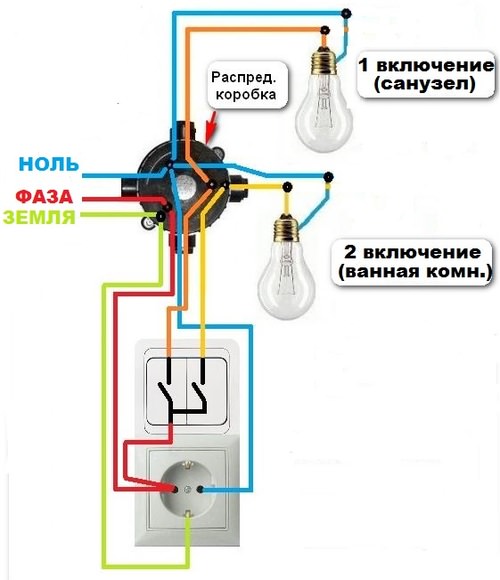
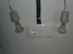
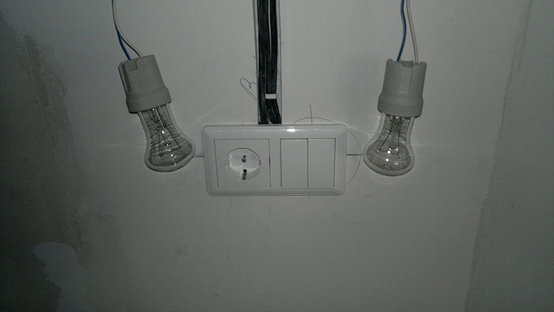
Example of connection from a nearby outlet
Let's consider a variant of connection of the control device by two fixtures according to the following scheme:
The location near the outlet and the switch is a common situation for small domestic apartments. Let's figure out how to connect double switch in this case.
Image Gallery
Installation of a pass-through two-phase circuit breaker
To control several lighting devices from different ends of the room, use a two-phase pass-through switch. It looks like an internal device for two pass-through ones, united in a common decorative case. There are two groups of terminals in it, which open the supply of current from one pair of electrical wires to the other.
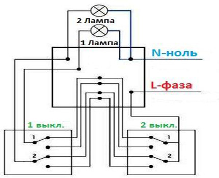
When conducting a loop-through connection, it is important not to confuse the pairs of conductors, so that both switches close the contacts of one of the two electrical circuits
How to install:
- The phase conductor from the wiring box is routed to terminals 1 and 2 (right), which are connected together in the circuit.
- From the switch, there are already four phases that lead to the box, and then to the second switch.
- From the switch No. 2, two phases pass (not intersecting). They lead to the box, where they connect to two independent conductors leading to the fixtures.
When performing the installation, you can first conduct one pair of wires, and then the second, so as not to confuse them, otherwise the circuit will not work.
Connection to power supply system
Determine that the wiring is carried out exactly according to the new system, you can by cable laid. It will be three-core with single-phase power supply or five-core with three-phase power supply. One of the wires of single-phase power supply will be a phase marked with a brown or red color, the other with a neutral (zero) marked in blue, and the third with a protective wire marked with a yellow-green color.
To facilitate identification, alphanumeric characters are used:
- A, B, C - phase;
- N is neutral or zero;
- PE - protective.
The difference of this connection scheme is in the additional protective conductor PE, which is output directly to the fixtures.
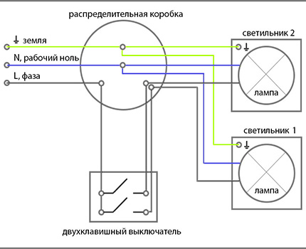
The wiring diagram of the TN-S wiring accessories involves a connection to the earthing system
After connecting the wires to the working mechanism, they are pressed closer to the body, and then installed in the sub-socket. Fasten in the mounting box with clamping lugs or bolts. Put on the decorative case and keys.
Before assembling the whole structure, turn on the light and make sure the lighting system is working
Video to help self-electricians
The available video for the installation of a simple electrical circuit you can see here:
When carrying out the installation of the power network or its components, it is necessary to follow the above instructions correctly. If you still have doubts about how to properly connect a light switch with two keys to the network, it is better to contact a professional.
Two-key light switches are widely distributed: they can be found in most buildings, both domestic and industrial. Such models are designed to control groups of different lighting devices, usually in large rooms.
However, two-key devices are also popular in small rooms, when one key, for example, controls the general light, and the other - the local one.
The scheme for connecting a two-button switch is not too complicated, but it has its own nuances, which will be discussed in the article.
Design Features
Switches are classified by several characteristics.
Posting type
Open or concealed wiring can be used, which affects the type of enclosure and the way the hardware is installed.
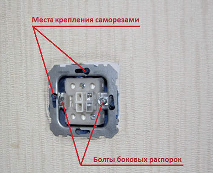
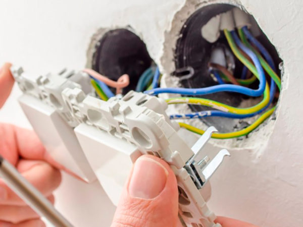
If it is an internal installation, then a mechanism is used, including sliding slats, which secure the device inside the wall opening.
The nest is made with perforators with crowns from the winning or technical diamonds. Initially, put a piece of plastic or metal, and then the main structure.
Turning the screws of the spacer mechanism the strips are set in motion and directed to opposite sides of the landing hole, as a result of which the body is securely attached to the wall.
A variety of contacts
The two-key switch can be equipped with a screw or clamping contact. In screwed contacts, the bare wire is fixed with a screw and a pair of metal plates, which is very reliable, but if the wire is too short or the cross section is incorrectly selected, the contacts will be greatly overheated.
As a result of overheating, the clamp is weakened, which requires regular pulling, since without this the contact will completely open or the elements of the device (wires, plastic) will fire.
In clamping models, the end of the wire is fixed by a plate held by a spring, which makes it possible to create a reliable and, most importantly, stable contact.
Housing material
The components of the switches are made of plastic or ceramic. On each hull, the permitted indicator of current and power must be indicated without fail.
Products made of ceramics can cope well with thermal effects and are best suited for systems with high loads (10 amperes, 220 volts, up to 2300 watts).
Plastic modifications are designed for lower currents (3 - 6 Amperes).
Criteria for selection of the switch and other components
Before connecting a two-button switch, the question of the required network characteristics and type of wiring, power ratings of consumers, current strength and cross-section of wires should be resolved.
For a lighting device having two groups of bulbs (one 100-watt and three 40-watt), the power consumption is P = 220 W. To calculate, we use the formula:
For such a load, you need a two-button switch with a 3-amp plastic housing and a 0.75-mm wire cross section.
In another case, it is necessary to provide a large room with lighting, where two groups of 8 light sources are used with three 80-watt fluorescent lights for each lamp. Power characteristic: P = (80 х 3 х 8) = 1920 W.
In the above example, you need a ceramic two-key switch with an allowable load of 10 amperes. The wire section is selected according to the special tables available in the PUE. For the most part, a three-core copper cable with a cross-section of 0.75 to 1.5 millimeters is used.

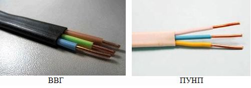
The most common types of cable are:
- VVG - cable with three copper wires and PVC insulation in a common insulating jacket;
- PNPP - stands for flat installation wire. Used to create hidden wiring without strobirovaniya. It is fixed on the walls with the help of brackets, and on top is masked with a plaster layer. The cable is equipped with a double layer of insulation made of PVC, a plastic sheath.
Device
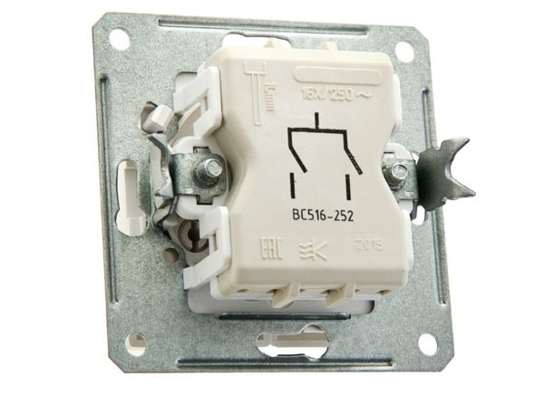
Switches with two keys are three-contact mechanical devices. One of the contacts is common (motionless), and the other two are independent of each other. When the button is pressurized, the brass plates are brought to the common contact, as a result of which the circuit is closed.
Two-key switches can be in six positions:
- two positions for one key (on / off);
- two positions for another key (on / off);
- two positions for both keys (on / off).
With the help of the above keys and their switching, the lighting groups that are connected to the switch are controlled.
Connection diagram
Connection of the two-key switch to the mains is carried out through a junction box. Three copper cables are sent there:
- from the distribution board;
- from the switch;
- from a lighting fixture with two groups of lamps.
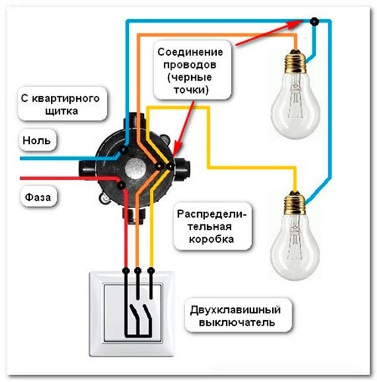
The blue wire is connected directly to the zero of the lighting device. The red wire is routed to the common switch contact. The green-yellow wire is connected to the ground terminal of the chandelier. A pair of the remaining movable contacts is joined through a junction box with unused terminals of the lighting devices.
If you need to connect two lamps for different rooms, and lighting control is carried out by a two-button switch, four cables are sent to the switch box:
- from the distribution board;
- from the switch;
- from two lighting devices.
The connection scheme remains the same as above. Green-yellow grounding wires are combined into a single contact. Then the contact is routed to the grounding bus of the switchboard. Free wires are isolated and stored as a reserve for expansion of the system.
Note! It is important to observe the rules for the color of the wires only on two sections of the circuit for connecting the two-switch switch: from the switchboard the cable is directed to the switch box, and from the lighting device to the junction box. Starting from the output switch contacts, you can use wires of arbitrary color.
To test the system use a multimeter, which should work in the mode of ringing. Alternative measuring devices can also be used. The opening in the lighting circuit is always in phase (red wire).
This scheme is due to the need to ensure safety during repair work and when installing new customers. The phase is located by means of a screwdriver-indicator when the protective device is switched on at the switchboard.
Features of installation on walls
For buildings made of reinforced concrete and bricks, it is recommended to equip the hidden type of wiring, and the switch boxes and switches should be installed in pre-made stitches. Dipsticks are recommended to choose plastic. Such podrozetniki fastened screws, and then cover with a solution of gypsum.
Two-key switch can have two types of fixation:
- Sliding mechanism, in which there is an emphasis of the slats on opposite walls. It is important not to overdo it when tightening the bolts, as ceramics can crack.
- Galvanized plate, located on the perimeter of the body. It has bolt holes, with which the part is attached to the wall and wall. For fixing, use self-tapping screws and dowels.
Two-key switches (when it comes to external wiring) are often fixed with screws, as well as interchange boxes. Wires are laid in plastic cable ducts.
Conclusion
Having an idea about the peculiarities of the design of switches and what is the circuit for connecting a two-button switch, it is much easier to select the right elements of the system correctly.
With these basic knowledge, it is possible to connect the switch yourself, without resorting to the help of specialists.
In residential and utility rooms there should always be light. For lighting, a group of light bulbs are used, the convenience of using them directly depends on the availability of a suitable switch. They are single, double and triple, but the most popular is the double one.
Two-key switch
The device consists of the following elements:
- Plastic housing.
- One input and two output terminals.
- Two keys.
- In some types - the light indicator.
Principle of operation
The device, with the help of its individual keys, it is possible to feed and interrupt the current going directly to the lighting fixtures.
Advantages and disadvantages
- With the help of different keys it is possible to switch on and off certain groups of lamps.
- Saving of the cable during installation (you need one), because the installation of two single switches requires the laying of separate ones.
- If it is installed for a large number of light bulbs, they can only include part of them (light adjustment), and this saves electricity.
- Used in rooms with high humidity.
- It does not require special care.
- Ease of installation.
Nuance: The body is made of strong plastic, but can burst from a strong physical impact.
How to connect with their own hands?
Before starting work, it is necessary to familiarize yourself with the scheme and prepare the necessary tools, otherwise the process will take a lot of time and effort. Given all the nuances - the connection is possible by an ordinary user, rather than a professional electrician.
Required Tools:
- Switch and plastic mold (glass).
- Screwdriver and figured indicator.
- Crimp terminals and special tool (crimp).
- Construction knife.
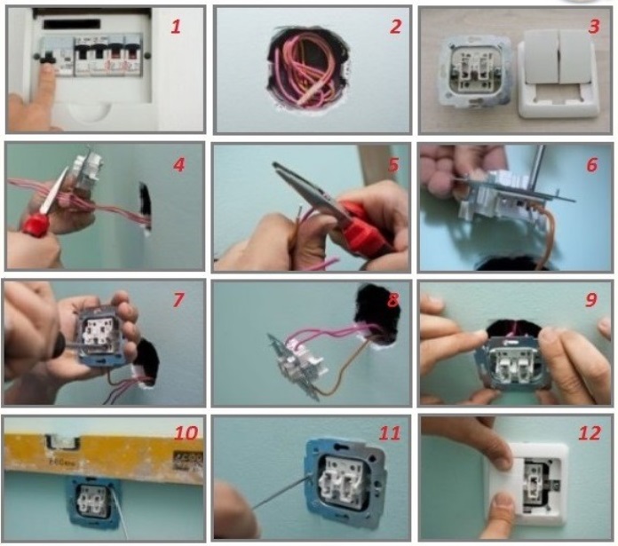
Step-by-step connection process:
- Initially, the power is turned off all over the house or apartment, by means of a switch in the switchboard block.
- The switch is disassembled: the keys and the housing are carefully removed to allow access to the terminals.
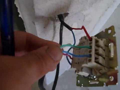
- In a suitable hole in the wall a special plastic mold is mounted, which protects the entire mechanism from various undesirable factors. A three-core cable is passed through the hole in the housing.
- The edges of these veins must be cleaned from insulation. Using a knife is cut approximately 1-1.5cm, the main thing is not to damage the copper or aluminum base.
- On the edges of the veins put on the crimp terminals and inserted into a special crimp (pressed). This contributes to their protection in the process of clamping the bolted connection in the switch.
- From three wires it is necessary to calculate the phase. To do this, the room is connected to the current, and the end of the indicator screwdriver alternately leans against the bare tips. If the diode in the middle of the plastic transparent screwdriver caught fire - this is the phase. After finding the right wire, the room is de-energized again.
- The end of the input phase is placed in the opening of the switch and clamped with a screwdriver. As a rule, it is located at the top and the manufacturers are marked with the "L" symbol.
- The ends of the other two wires are placed in the terminals, which are located at the bottom.
- When the wires are fixed and checked - the body and the base must be combined and placed in a plastic base in the wall and fasten (alternately, twist the side bolts that extend the metal petals). Attach two keys (covers).
- Then the switch in the switchboard block resumes the supply of electricity throughout the house, after it is checked for proper operation and proper functioning.
Safety precautions
Work on connecting the appliance is carried out only when the room is completely de-energized. Neglect of this condition threatens to damage the body with shock, burns or death.
All used tools should be with insulation elements (plastic handles, housing). For complete protection of a person - it is desirable to put on your hands special gloves and walk in rubber shoes (materials - dielectrics).
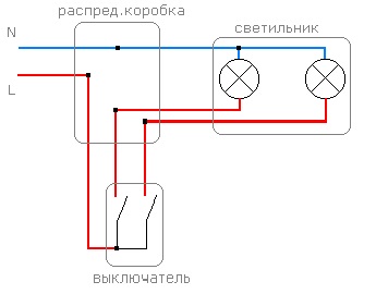
Scheme of connection to two groups of light bulbs
- To divide the flow of electricity in the room should be mounted in the wall - this is the key element. Initially, it starts a two-wire cable from the shield unit (one wire is connected to the phase, and the second to the zero).
- From each group of lighting devices, a two-wire cable is also laid to the box. In the cable there are two wires with different in color insulation (for example, red "zero" and blue "phase").
- Three red wires are connected together by the twisting method or on the terminals. They serve as an inseparable base connected to all light bulbs or other devices.
- The phase center wire coming from the "shield" is the incoming (main) and is fed directly to the switch to the desired terminal. Blue wires from different groups of light bulbs are not connected together, but pass through separate wires to the output terminals of the switch.
In total, the following elements should be obtained in the box:
- 1 main phase wire.
- 1 output for the first light bulb or group.
- 1 output to the second group.
- 1 wire "zero" combined with all the light bulbs (twist).
Taking into account all the nuances of connection according to the scheme it is clear that the phase wire has a key role in the process of switching on and off groups of bulbs from the power supply. Zero - serves as a complement.
Recommendation: Making the twisting of the veins together - their ends must be thoroughly cleaned from the insulation and not less than 4-5 cm long. Clamp the wires preferably with pliers in such a way that a braid (pigtail) is obtained. The bare area should be wrapped around with insulation or a protective cap.
Tip: to reduce the waste on the conductivity of wires from the box to the switch can be used one three-core, the veins in which serve as phase distributors.
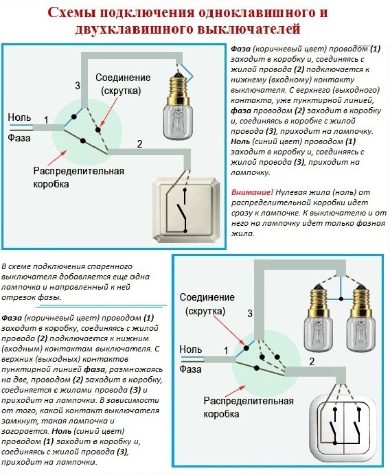
Scheme of connection to one light bulb
This method is much easier to connect the necessary lighting device and is almost similar to the previous version. On an example it looks as follows:
- From the "shield" to junction box a two-wire cable is supplied.
- The identical cable is from the light bulb.
- The wires with zero index are connected together and isolated.
- The main phase conductor is connected to the proper input of the switch (terminal block "L"), and the output wire to one of the two lower terminals.
In this case, one of the two-button switch buttons is inactive.
Connecting the switch with the light indicator
Some switches have at the bottom of the transparent window, near which is the LED. It is designed to visibility of the switch in the room at night and the visibility of its operation from the main electricity supply system.
Connection Process
- From the diode goes two thin wires for a bundle with the main power wires.
- One tap must be aligned with the main phase conductor and fixed in the terminal block.
- The second branch can be attached to any branching phase.
- After that - the lower part of the device keys will be illuminated, which means full functionality of the switch.
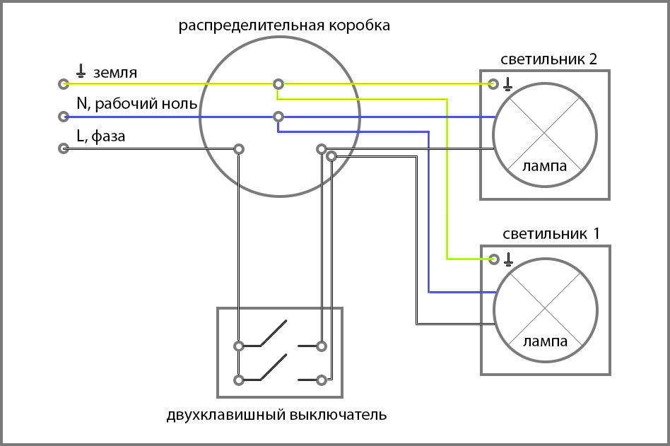
Diagram of connection of a two-button switch
- Do not connect the appliance while the mains power is on.
- All work must be carried out with working tools.
- The switch in the complete assembly must be of high quality.
- It is recommended to purchase the device with fixing clamps, which allow fixing the wires once. Switches with bolt-hole fastening can damage it, and full pressing reduces wear resistance and can cause arcing.
- In the process of connection, there are often cases when it is necessary to resort to the process of twisting the wires (serial connection). In such cases, it is necessary to carefully clamp the connecting wires and wrap them with insulating material, and on top of it, put on a protective plastic cap. Faced with this problem and confusion with the connection scheme - it is better to contact a qualified specialist, so as not to de-energize the entire apartment.
Conclusion
The most advantageous option for the room is the installation of a two-button switch, because with it you can turn on the light in necessary quantity (brightness adjustment) and in the respective rooms. The main thing is to install the switch correctly adhering to safety precautions, and it will last for many years, without additional intervention or repair.
Electrical installation of switches with two keys is a separate field of technology and it, like other directions, continues to develop actively. So, new modifications are constantly being created and the existing designs of electrical devices are being improved. Next, we'll look at how to connect a switch or outlet.
With concealed installation, the plant is manufactured in universal mounting boxes, which are mainly made of plastic. FROM reverse side boxes are placed stubs, which can be easily removed. They are designed to introduce wires of different diameters and tubes that perform the function of protection.
Connection to hollow walls
If the question arose how to connect an outlet or switch to a hollow wall, then for this purpose special boxes are provided, which are equipped with screws with paws.
Through them, the fixation of a device on the surface of the wall. The holes are drilled with a drill. The nozzle is selected in accordance with the diameter of the box. With it should match the diameter of the cutting part of the nozzle.
How to connect a switch with two keys to concrete walls
If you are going to install a box in concrete walls, then the connection to it is done by means of channels, which are made by wall panels, or through plastic corrugated tubes, laid in strobes.
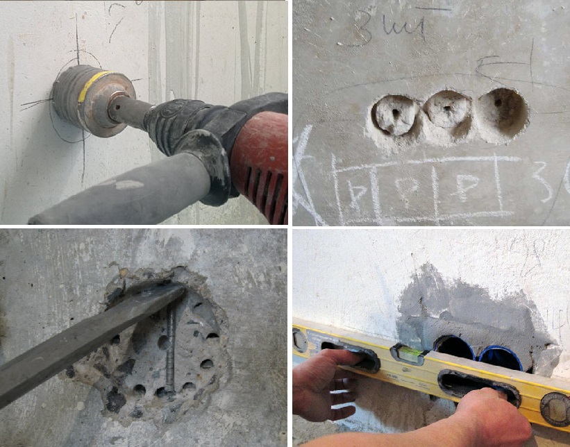
Fixation of the box is done with a conventional cement or gypsum solution. For the same purpose, you can use special glue. But as for alabaster, it is undesirable to use it, because its volume increases when it dries.
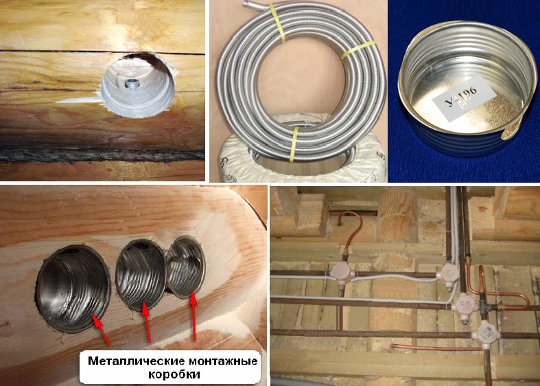
Connecting a switch with two keys in a wooden wall
In this case, a hole is made with the help of self-tapping screws, and a box is already installed in it. On the circumference of the box there are plugs or special elastic membranes, designed to seal the areas of input wires. It is possible to connect the boxes to blocks.
The domestic market offers a wide range of products from ABB and Busch-Jaeger Electro, as well as Spelsberg, Legrand, Simon and Brichino.
Many modern models have a spring (screwless) connection of contacts. Naturally, in this case, the connection of the switch or socket is made easier. And to provide switching of two conductors, in most outlets special paired terminals are installed. They are convenient in case they are done parallel connection several outlets in one unit.
The new switch models have a special contact shape, which makes it possible to switch off quickly, without intermediate positions.