Requirements for connecting the circuit breaker. How to properly connect the circuit breaker: useful advice for the home master
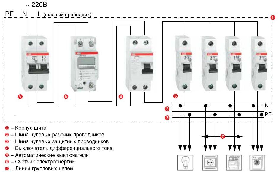
After major repairs of electrical wiring in the building or when laying new electrical networks, there is a need to reliably protect the conductors from overloading, as well as to increase their service life. This gives the possibility of reliable operation of electrical appliances. For protective purposes, use automatic circuit breakers, which cut off the supply of electricity to the consumer when the specified power is exceeded or in case of a short circuit. These devices are installed and connected in a switchboard. In this article, we will talk about how the connection of automata in the shield with a comb and jumpers is performed.
What is important to know?
Depending on the number of phases at the input, they distinguish:
- single-phase network;
- three-phase network.
By the way of installation:
- by means of a tire (comb);
- bridges of stranded wire;
- bridges of solid wire.
Based on the initial data, it is necessary to select the electrical fittings and conduct, choosing from the listed, the desired method of connection to their electrical network.
Installation works for single-phase and three-phase circuits differ slightly. AT single-phase network One circuit is applied to all circuit breakers at the input and single machines are used. For three-phase network I use triple automatic machines in case of connection of a three-phase load or it is possible to put single ones on each phase separately, in case of single-phase load.
Ways of connection
Comb
For convenient and qualitative connection of circuit breakers in the shield, a bus can be used. Depending on the number of phases, you can choose the correct comb:
- for single-phase circuit - single-pole or double-pole;
- for three-phase - three- or four-pole.
The installation is very simple. Under the required number of circuit breakers, a comb with a certain number of poles is selected. If the comb is for more contacts - the excess is removed (you can hacksaw the metal). Completing the installation, insert the tire simultaneously into all the clamps of the automatons and tighten the screws. The outputs are mounted according to the scheme. In more detail about that, we told in the corresponding article. The video below demonstrates the connection technology:
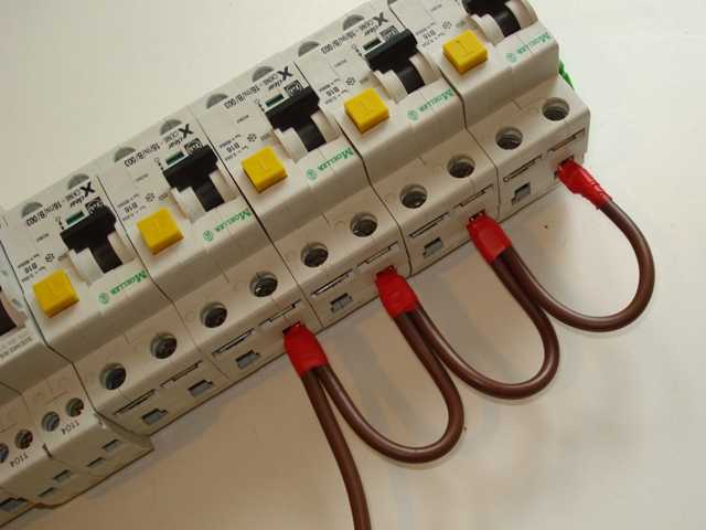
Lintels
This type of connection is used in the case that there are few automata and enough space in the shield for easy access to the contacts. This method can be used for both single-phase and three-phase circuits.
To perform work in the shield, it is necessary to prepare jumpers of suitable length and section. The cross-section of solid conductors for connection of protective devices must be sufficient for the estimated power consumption. About that, we told in the relevant article.

Ideal is the option of manufacturing jumpers in a non-explosive way:

From one piece of conductor, bending it with the help of pliers, make a jumper that will connect all the circuit breakers of the circuit. The wire must be bent with the required distance. After this preparation - remove the insulation from the ends by about 1 cm, strip the wire, removing the oxide film with a knife or sandpaper.
It is important to remember that in this case the phase and neutral wires do not have to be tightly pressed together. This is due to the fact that during the operation of the electric network they are heated, and an unwanted phase-to-zero connection can occur due to the heat-softened insulation.
You can also use a stranded wire of the desired cross-section to connect the automata in the shield to the loop. But in this case, it must be stripped from the insulation by 1-1.5 cm. At the end of the wire, it is necessary to put on the tip, which corresponds to the diameter of the wire in diameter, and compress it with the help of special mites. A series connection of several automata is permitted.

In the absence of a proper tool and tips, it is acceptable to use a soldering iron to bare the bare wire. Tin or solder gets between the strands of the stranded conductor, forming a fairly strong connection of thin veins. And, although this method is considered less reliable than the previous one, it is often used in connection with ease of use.
In the absence of soldering iron, the installation can also be carried out with conductors that have been removed from the ends by clamping them directly into the machine. This type of installation is the least reliable and at high loads it threatens the heating of conductors in the place of unification and, accordingly, increased fire danger. This type of connection is not very aesthetic appearance and low reliability.
The connection of automata in the shield by one's own hands using a stranded insulated conductor must be performed in accordance with the previously drawn up scheme. Circuit breakers in this case can be used not necessarily one manufacturer. Their dimensions may differ, because the installation with a flexible wire allows you to do this.
Conducting permissible electric current and breaking power when the rating is exceeded. It serves to protect against overload of electrical circuits. A single-pole machine provides protection for only one wire.
The device and the principle of operation
The main characteristics of the circuit breaker are the rating and the tripping speed. A single-pole automatic device is triggered by two mechanisms: thermal and electromagnetic releases. The first disconnects the circuit in the event of an increased load for a long time, and the second - instantly, with a short circuit.
The thermal protection device is a plate made of bimetal. When it passes a current above the maximum permissible, it gradually warms up and flexes, pushing the lever that turns off the machine. After cooling, the plate returns to its place, and the switch is again ready for operation. To enter the operating state, you must connect it manually.
The electromagnetic device consists of a coil with a core inside it. When an short-circuit current passes through the winding, an electromagnetic field arises that moves the core, which turns off the machine. In this case, the power contacts are disconnected, de-energizing the circuit. Since a large current passes through them, an arc arises. It enters the arc chute chamber, where parallel metal plates are located. With their help, the arc crushes and disintegrates.
The automaton is also used as a switch by turning manually the control handle.
Use of a single-pole circuit breaker
Electrical wiring in the apartment branched into several groups. The connection of a single-pole circuit breaker is made by breaking the phase wire. It is mounted on the DIN rail, and the power cable is inserted into its upper terminal. The protected wire is connected to the lower terminal. If the wires are pressed with screws, they must be tightened with a little effort.
As a rule, the upper terminals of single-pole automata are connected to the power supply through the comb, and from the lower ones the wiring is made in groups. Multiple standby units can be installed.
Marking
The circuit breakers are standard-labeled, which is read from top to bottom. 
The body of the device shows the values of its main parameters:
- the trade mark is EKF;
- number of the series - BA47-29;
- the characteristic "C" and the rated current for a single-pole automatic device is 25A;
- the rated supply voltage is 230/415 V;
- maximum permissible short-circuit breaking currents - 4500 A;
- class of current limitation - 3.
By brand, you can identify the manufacturer. Automatic machines should be chosen from well-known brands: Legrand, ABB, IEK, EKF, etc.
The inscription on the 230/415 V machine means that the device is capable of operating in single-phase and three-phase networks. Most of the devices in household wiring have this capability.
The rated current is the magnitude of the current strength at which the machine does not operate for a long time. When it is increased by 13%, it will turn off after 1 hour. The greater the value of the continuously flowing current, the faster the response. The main purpose of the machine is to prevent overheating of the wiring when the load is connected. It is important that the current allowed for the conductor is greater than the nominal value of the apparatus, and not vice versa.
Time-current characteristic "C" means that the operation of both trip mechanisms occurs after a five-fold increase in the rated current. It is suitable for lighting and most household appliances. If there is an automaton with such a characteristic in the entrance, then the apparatus with the characteristic "B" should be installed in the main panel. This means that for all other similar characteristics it will work faster. Then do not have to run into the porch and turn on the gun there. The correct selection of a device with a suitable characteristic provides the desired selectivity of operation.
The maximum permissible breaking current shows its maximum value, at which the machine can be turned off at least once.
Number of poles
If you choose a single-pole or two-pole machine, here it is important where to install it. On the main input of the housing flap, a two-terminal network should be installed. This will reliably disconnect the wiring of the house during repairs, when you should turn off the phase together with the neutral. When two wires are entered into the house, it is possible to install an automaton with one pole. In the presence of a grounding conductor, a two-pole input automaton is placed.

At each branch of the home network, a single-pole machine is connected with the RCD.
If the apartment is powered by a three-phase circuit, you should install a four-pole automatic machine at the main input.
Single-pole automatic machine: price
A single-pole automatic is cheaper than the rest in a line with a large number of poles. Products of domestic manufacturers can be bought for 40-50 rubles. And imported brands are already 150-200 rubles. It is important to choose the machines in terms of quality-price ratio, and not those that are cheaper. 
Errors in the selection of automata
Choosing automatic switches, users make a number of mistakes.
- They focus on the total power consumption instead of protecting the wiring from overload. Installing a powerful machine on weak wiring leads to its overheating. It is important to select the device on the wire cross-section.
- Often, the same machines are installed on all lines, which causes some of them to be overloaded. For outlets need protection at 25 A, and for lighting - 16 A. The line leading to the garage can be heavily loaded with powerful power tools. Here it is expedient to establish an automaton for 32 A.
- Do not choose automatic machines for the price. It is better to buy products of famous brands, where quality is guaranteed.
Conclusion
In order to select the required single-pole automatic machine without errors, it is necessary to understand the marking applied to the housing from the front side. The characteristics of the device are selected depending on the type of load to be connected and the section of the wiring.

Automatic switch (VA) - a device capable of switching off electric power for consumers without human intervention, in the event of an overload or short circuit in order to protect the electrical circuit from further destructive consequences and to prevent a fire.
The circuit breaker will stop supplying the entire apartment or de-energize a separate group in electrical network, until the cause is clarified and eliminated.
Functional capabilities of the circuit breaker
During an electrical network overload, circuit breaker to cut off electricity can operate in different ways, depending on whether the cable is hidden or openly laid? What is the ambient temperature? The machine can trigger a shutdown during an overload from several minutes to several hours. As soon as the load increases to the specified nominal value of the circuit-breaker, for example, if the automatic input is set to 40A, as soon as the current increases to 40Amper (8.8 kW), the machine will fire.
You have purchased and installed a washing machine - it's great! But soon you had an annoyance - the automatic switch was often knocked out. What to do? How to be? It is not advisable to increase the rating of the circuit breaker, for example from 16A to 25A, old aluminum wiring will work at the limit. Which exit? It is better to separate the washing machine from the general group in the network and conduct a separate three-core copper wire from the panel and install a circuit breaker at 20A, if the rated power washing machine 2200 watts.


Which circuit breaker should I install?
Counting the value of the circuit breaker, proceed from the wire section, the temperature load, and also from how the wiring is laid - hidden or open. Take into account not the limiting current transmission, but "quiet", i.e. there should be a good margin of safety or it is easier to say that the conductor is not heated because of the overvaluation of the machine. In the other case, if the conductor has a high throughput, it is not necessary to understate the denomination of the machine - it will constantly kick out.
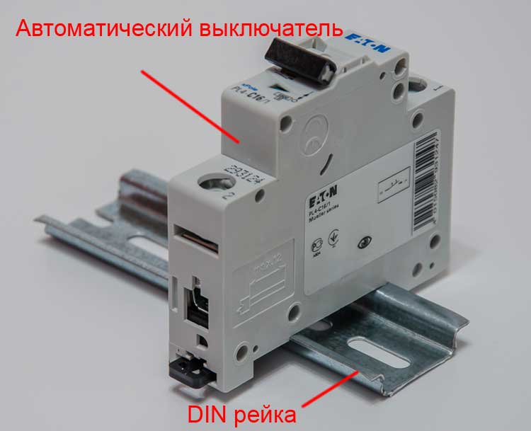
Sectional circuit breakers are "put" on a plate, called a DIN rail, built into the switchboard. The circuit breakers are 1P (pole), 2P, 3P, 4P. The last two are installed in a three-phase network. In a single-phase 2P network, the automaton is most often installed at the input.

The values of the rated current of circuit breakers at home: 2A, 6A, 10A, 16A, 20A, 25A, 32A, 40A, 50A, 63A.
Where do not install circuit breakers?
On individual groups put 1P, you can 2P, but this is not economical, both in terms of money and in the space of the panel. It is known that in France, according to the rules and regulations, only two-pole switches are placed. It can not be said that they do not save space in the panel. The fact is that, the French bipolar switches are our single-pole switches. Do not set the 1P circuit breaker to zero. It is not recommended to break zero separately from the phase. All zero conductors are attached to the common zero bus. You can break the zero at the same time as the phase, in which case you need to put the 2P automaton.
To effectively protect the electrical circuit of your home, you should consider replacing fuses or plugs, to a more secure, reliable and cost-effective circuit breaker.
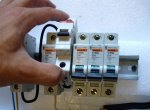
If you've ever seen how professionals mount, then there's probably an opinion that there's nothing easier than installing the circuit breaker yourself. Clicking, fitting, pasted the wires, tightened the bolts, put next one more and so on. The installation of an electric shield in the photo above for two electricians took about an hour and a half, of which 30 minutes for checking 380V.
But, despite the simplicity of the process, the connection of the circuit breaker has its own subtleties, which you need to know about before the installation.
Fixing the machine in the power shield
Despite the strict regulations in the energy sector, with respect to the fastening in the shield, the PES are quite loyal, because (if translated into Russian) requires the reliability of fastening, allowing multiple switching-off of the device without deformation and displacement. That is, it must be so clipped that it does not move when turned on. And further, though stick. But in fact, up to now only three methods of fixation are used:
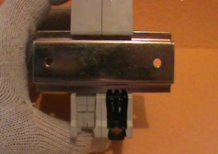
- In the locking socket of the power shield. This standard was transitional and very rare. The machine "presses" into the socket with the latches, where it is located. To remove - you need to pull off the latch with a screwdriver;
- On the bar in which holes are drilled, and the thread is cut. Planck has a stock of space and it is possible to make connection of an additional automatic switch at any time - you need to drill holes, cut the thread and put it. To put, of course, it is simple, but here to drill in a guard and to work a tap is extremely inconvenient. Nevertheless, now this is the second most widely spread way, because there is still a lot of aging housing;
- The modern method is mounting on a DIN rail. For household purposes, now machines with a different method of installation are no longer available. In fact, this is the development of mounting on the bar, only in a simplified version and with the possibility of simply building up a package of automata.
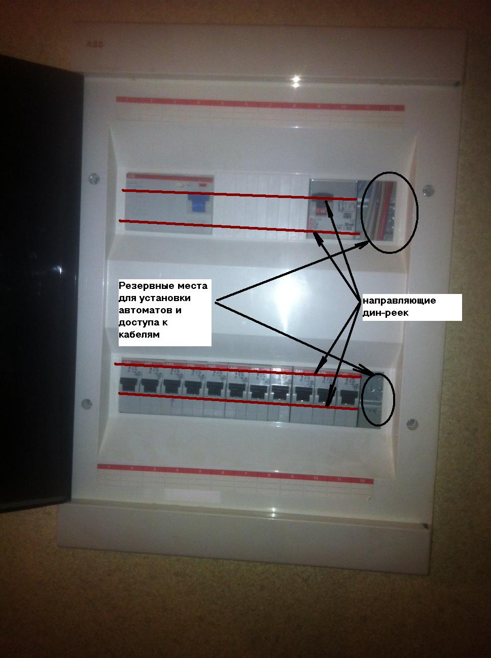
We knowingly consider separately the fixation of the automaton in, the installation of a circuit breaker - this is 40% mounting in the shield . There are several points to take into account: access for easy replacement, disconnection, change of the circuit of connection of circuit breakers and the possibility of simultaneous dismantling of the whole set of automatic machines without switching off each.
The subtleties of connecting automata
If you want to turn on one machine, it will not cause questions even for a novice electrician. However, one automaton is such an anachronism that we will even consider this case. How to connect a circuit breaker, if one is indicated on the machine itself, with a phase diagram - zero, but this is an exception to the rule. The standard situation is when several switches operate on an apartment (a floor in a private house). How do I connect in this case? Of course, first you need a circuit for connecting the circuit breaker (first).

- The supply cable (phase) is connected from below .
- must be correct. There should not be too much bare wire and should not get into the contact group to get part of the insulation. The easiest way to measure the right piece of stripping is a toothpick.
- After the installation of the circuit-breaker is completed, it is necessary to check the fixation strength on the de-energized shield, strongly stirring the machine on the rail (bar). Displacement in this test will require more reliable attachment.
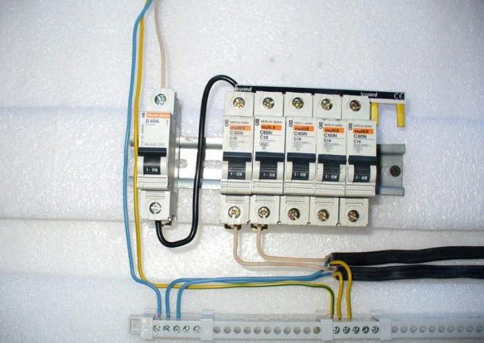
- The circuit of connection of automatic switches should look like a comb - a zero cable from above, from one machine to another, the phases from below - for each circuit its own. Of course, separately the earthing of the earth. One for all.
- A separate consideration deserves. On the one hand, the machine put in front of him will allow to de-energize the apartment and stop charging even reactive energy. On the other hand, improper sealing of such a machine creates additional problems in communicating with the energy sales companies.
These are all standard procedures. Now about the features.
End-to-end switching of automata
This is a circuit for connecting a circuit breaker, in which each next has a common zero wire with the previous one.
We will explain. Plus - the simplicity of the circuit and the installation. Minus is the break of the zero wire when one machine is shut down. As an option, additional zero "bridges" through the machine. That does not solve the problem of disabling two machines at once - zero will be disabled. This is inconvenient, but with such a scheme you are guaranteed to be protected from a breakdown, which may be. Sometimes a "zero bus" scheme is used, in which each automaton is individually switched to zero, and although the connection of the circuit breaker remains visually the same, the physics of the process varies significantly. When you turn off one machine, the second, third, etc. continue to work, having its connection with the zero bus. By the way, any installation of the circuit breaker should begin with the evaluation of the zero bus and the ways of separate input of wires for each device.
Isolation of the power wire in the contact group is unacceptable! Very carefully clean the wires! Fastening the machine to the bar, DIN rail or socket must be isolated from the power cables! Rubber washers for screws are never superfluous when mounted in the shield.
Install the circuit breaker in the shield
Now about the installation itself. The case of the machine has the inclusion marking - that is the question where to screw the phase is not worth, how to connect the circuit breaker to the network - is drawn on the machine.
Before mounting, unscrew the bolts of the contact group, measure the depth of the entrance (the length of the stripped part of the cable), check the presence of threaded latches on the DIN rail (some models have a bottom on the bottom, which further strengthens the screw on the rack with a screw).
The very procedure for installing the circuit breaker begins with "fitting". We put all automata on the latches on the rail, we estimate the distances between them, the availability of space for additional (if necessary), as well as the possibility of marking the connections. Mark all the wires separately (regardless of color), phase, zero, earth, after which we clean the cables.
We clean the cables in the shield, where there are automatic machines on the rail. This is done in order to accurately estimate the necessary length of the wires.
We check the quality of the earth-zero wire contact. Ideally, the distance from each neutral wire to the ground cable should be approximately the same. That is, 10 and 20-cm see, it's the same, but 20 cm and the meter is unacceptable. PES give a spread to 60% . That is, the shortest input is 10 cm, if the longest is 60 cm. We orient ourselves on this.
We are convinced that the circuit of connections of automatic switches is correct, the "layout" is correct, everything is ready for installation. We turn on, without fixing it, holding out the wires, the first machine, check the commutation and check the line. We check simply: in the socket carefully insert nails, pliers with insulation. After that, drop another nail.
If done correctly, the machine will turn off the line. In order to avoid "nailing the nail", it is better to throw it with a swing. A short, if something is wrong, but the nail will bounce - the inertia will not allow to weld and the wiring will not suffer.
Having thus verified the line (if you are going to connect and install everything yourself, just one machine, the rest you do exactly the same), you can end the process.
Step-by-step installation of the circuit breaker
- We de-energize the shield!
- We set the wires in the sockets of the contact group of the machine, make sure that the insulation did not fall under the tightening screw, and slightly attract the wires. If there are several automata, repeat with all at the same time.
- After assembling the "spider", we check whether the circuit of each circuit-breaker is correct. We check visually, tracing the chain of connections and checking what was drawn earlier.
- Without taking out the wires, we put the machine to the click, we check how much the installation of the circuit breaker on this rail is reliable. This is not a repetition, it's a reminder that the multiple removal of the machine from the rail slacks the clips and clips!
- We put the rest of the machines in a row, checking on each the reliability of the fixation.
- Selectively check the line of the machine, just as described a little above.
- We tighten the wires with screws in the contact groups of the machines.
- Turn on the power of the flap.
- We check the network sections, giving the maximum load.
If everything is all right, we are proud of the work done ".
Practical recommendations for the selection and installation of circuit breakers
- Before deciding how to choose an automaton, you need to make a calculation, but, having calculated the planned, leave a margin of safety - only in the other direction! If the calculation gives 22 Amps, buy 16, or 20-t. But not 25.
- When installing, observe the rule in sequence . You can not connect machines "through one", which is simpler, so professional electricians sin. You do for yourself, so do it right!
- Pay attention to the screws - they must be made of stainless alloys. It is important that they are the same, at least for the composition of the material!
- The very dyne-rake must also be securely fixed, one of the mistakes of novice electricians is fixing it on the spacer. Be sure to fix it with screws!
- Thick wires are not suitable for thin mounting. Use terminal block , in it you can collect hard wires and lead flexible wires where necessary.
- Remember that design is not the last thing. Practicality is also not something that can be neglected. Example in the photos below. Remove the panel in a couple of minutes, and on the wall it does not look like an electrical box.

And most importantly, in the production of this kind of work, remember the main rule - step-by-step actions . Take a step - check yourself . Then take the second step. And so on, until "by smell" you learn to distinguish the earth from the phase, and zero from the ground.
Electric guards located on staircases apartment buildingsare fully in charge of electricians from management company. However, one must know the purpose of electrical devices enclosed in a metal box. Let's try to figure out how to install the circuit breaker, if there is an urgent need.
Information on electrical devices, known from school physics lessons, is not enough for practical application.
Ordinary consumers are more likely to encounter automatic circuit breakers, since they are triggered by network overloads. It is not enough simply to return the lever to the usual position, it is necessary to understand the reasons for the shutdown, otherwise the situation may repeat in the near future.
To orient in the stuffing of the switchboard (which, by the way, is an obligatory element of the power system of private houses), it is necessary to know the composition and purpose of all devices - impulse relays, load switches, RCDs, etc.
Do you need to be able to change the automation yourself? We recommend to study the theory first, and at the first disconnect - and practice. The fact is that it is not always possible to quickly help professionals: on a day off, electricians rest on an equal basis with the rest. And if the house is located in the country or in the village, it is better to get acquainted with the electrical network and related devices thoroughly.
Design and purpose of the machine
Despite the name - "automatic", this type of circuit breaker works only in one direction - it opens the electric circuit (when exceeding the nominal value or overload associated with the simultaneous inclusion of several powerful electrical appliances). Enable, that is, close the chain, can only be the only way - manually.
Unlike simple single-key switch, the automatic device has a more complex device. Schematically, the classical version (without an electronic unit) looks like this.

The terminals are located at the top and bottom, with the upper connected to the fixed contact, and the lower one is closely connected to the metal plate, which plays the role of a thermal release. When the temperature of the material rises, the plate is deformed
There are ways to start the tripping process:
- manual control (on / off) with a small lever;
- effect of short circuit currents;
- excess load - exceeding the rated current parameters.
In order for a powerful thermal effect not to burn the switch, an arc chute (a set of copper insulated plates) is provided that cools and breaks the electric arc.
Electromechanical device selection
Taking into account load parameters and cable characteristics, it is possible to select a device for mounting in the switchboard. All the necessary information about the electromechanical device is on its front panel.

The first line usually indicates the brand of the product. It is better not to save, but to choose automatic device known manufacturer: Legrand, IEK, ABB, Schneider, Electric, Hager
Voltage, frequency and rated current
In the next line you can find information about two important characteristics - voltage and frequency. The most common "format" is 220 / 400V 50Hz. This means that you can connect one and three phases at a frequency of 50Hz.
If we take all the constructive views, then the correspondence between the poles and the voltage will be as follows:
- 1-pole - 220 V (1 wire - phase);
- 2-pole - 220 V (2 wires - phase / zero);
- 3-pole - 380 V (3 wires - phases);
- 4-pole - 380 V (3 phases / 1 zero).
The value of the rated current limits the use of certain types of cables - and this must be taken into account when choosing automation. Therefore, when buying a switch for the switchboard, check which types of wires are involved in the construction general scheme. In no case do not build on the maximum voltage in the network, otherwise the following may result.
Suppose, the purchase of new household appliances leads to overloading and constant knocking out of the machine. You will want to increase its power and replace it with a new one whose rated current is higher. As a result, during the power-up of several powerful devices, the machine does not work, but the wires overheat, resulting in a short circuit (the insulation will melt away, and an ignition will occur).

If the cross-section of the cable does not correspond to the load, it must be reduced (or, conversely, update the communication). But you can not choose a circuit breaker, focusing on the maximum load - only by cable
The circuit must be arranged in such a way that the weakest link is the automatic switch (not the wire), which is designed to protect against overload.
Is BTX important?
The letter designation of the time-current characteristic precedes the digital marking, which determines the rated current. To understand what the essence of BTX is, let's analyze the formula:
where l is the current in the network, ln is the rated current value, k is the multiplicity. The category depends on the multiplicity:
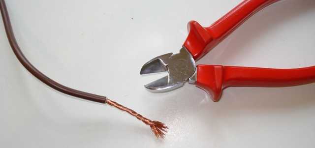
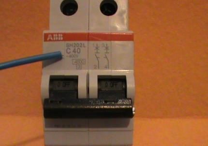
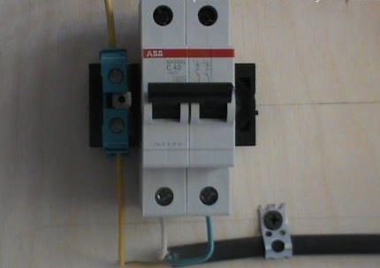
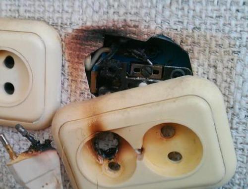
B-3 C - 5 D-10 The graph of correspondence is clearly shown in the figure: Three zones, painted in different shades, indicate categories of BTX: red - category B, blue - category C, green - category D The speed of the automatic response depends entirely on the multiplicity: the larger it is, the faster the shutdown will occur. For household use the listed categories are used, but apart from them it is possible to meet auto-switches with categories BTG G, K, L, Z. The B16 circuit breaker operates instantaneously at a current of 150 A, while D16 only after the plate has heated, after a few minutes. The most common category C is used in household and production, in networks with medium and small starting currents. Category B refers to high-speed, participates in schemes of old networks. It should be borne in mind that the speed of operation is affected by the ambient temperature. The dependence is as follows: the higher the temperature index, the smaller the current is needed to react the machine. Experienced electricians in the electrical switchboard equipment take into account this compliance and try to leave a little free space inside the flap so that there is no overheating due to the operation of a large number of devices. Do not forget about the rule of selectivity: from all protective devices embedded in the circuit, the first thing to work is that which is closer to the place of congestion. If the near automatic machine did not react, but the next one (suppose, access) has worked, the device parameters are not selected correctly. The number of poles in modern auto-switches can vary from 1 to 4, with 1- and 2-pole devices serving single-phase circuits, and 3- and 4-pole ones are three-phase. PKS is the ultimate (nominal) switching (disconnecting) capability. Its value indicates the value of the maximum short-circuit current (TKZ), at which the machine can still work. The parameters of the TKZ should not exceed the PKC, otherwise the guarantee is removed. If the automatic device several times provided protection from TKZ, its resource is most likely exhausted and replacement is required. In the home most often used devices with PKS, equal to 4.5 kA, but there are modifications of 6 kA and 10 kA (the latter are relevant for industrial use). And the last characteristic is a class of current limitation. The label can indicate 1, 2 or 3 classes, in some cases this indicator is not present. If it is not, the device belongs to the 1st class of current limitation. Each class denotes a certain reaction rate of an automaton for the emergence of a TKZ. Quality and cost depend on the class, because the higher the number, the more expensive the device. The duration of the automatons is approximately the following: Most modern switches belong to the third class. After you select the appropriate circuit breaker, you can proceed with its installation or replacement. Each element is a module that occupies a number of places equal to the number of poles (in the figure - samples of single-pole, i.e., 1 place). The size of one "cell" is 1.75 cm, two - 3.5 cm, etc. If you open the cover of the electrical panel, you will see that all the modules are fixed on a metal strip called the DIN-rail. The width of the plate is 3.5 cm, each module occupies 1.75 cm. Image Gallery The following tool is required for installation: The first thing that must always be done before any manipulation in the electrical panel is to de-energize it and make sure that during operation no one accidentally plugs in the power. For safety, you should use an indicator screwdriver and check for a lack of voltage. Next, take the pre-assembled circuit breaker and attach it to the DIN rail so that it rises in line with similar devices. If there is space left on the edges, it is better to fix the module with special stops - metal clips on the screws. Installation does not require special fasteners, since the latch is located directly on the body of the device, it is enough to lean it against the rail and press a little. To remove the failed device, the latch should be loosened with a screwdriver Connecting elements with multiple poles has differences: As you can see, the main principle of connection is that the input is connected to the upper terminals, the output is to the bottom ones. Wires, as a rule, are withdrawn into the shield. For ease of use, they are grouped using screeds. It is important to properly distribute the cable connection points. For single-pole devices: the phase coming from the RCD or input device is connected to the upper terminal, the phase of the circuit to the bottom Pull the ends of the wires to the appropriate terminals, position them freely, without stretching, and remove the excess wire cutters. With a construction knife or stripper, remove part of the insulation (the length of the bare wire is 1 cm). If you use an improvised tool, try not to damage the cable in the transverse direction, so as not to provoke the hall. Pulling the wires in the shield, try not to bend them, do not make as many turns and creases as possible, and also do not pull up like a string The phase connection can be equipped with a comb - a special bus with the necessary number of poles. Instead of the comb also use self-made jumpers from the wire PV3. Two wires in one terminal can not be placed, so they need to be crimped by the tip of the NSWR. Stranded wires must be crimped - attach the tip of the NSWR. A tool does not fit, use a special device that resembles a wire cutter, - a crimper Prepared wires are inserted into specially designed holes. After the wires are cleaned and inserted into the terminals, they must be fixed by carefully screwing the fasteners with a screwdriver The installation ends with the mandatory testing of the system: we supply voltage, connect all the devices in the circuit and check the presence of voltage in the area of the upper and lower terminals using an indicator screwdriver. Instead of a screwdriver, you can use a multimeter. According to the rules, the device must be marked to indicate its belonging to a particular chain. A similar marking must be present on the protective cover of the shield. Image Gallery And now we will try to understand the connection of an automaton with 2 poles to an electrical household circuit of 220 V. This means that at the input there will be 2 wires - phase and zero. The wire required for connection has 3 cores 2.5 mm in cross section (ВВГнгП 3 * 2.5), therefore, the maximum permissible long-term current is 25 A. We chose a two-pole automatic protection device, which looks like this: We need four contacts, two of which are at the top (incoming), two - at the bottom (outgoing). The fixing will take place with the help of fixing screws fixing the pressure plates On the surface of the body there is a hint - the circuit of connecting the machine. By marking, we determined that the machine corresponds to the wire cross section - C40. This means that the current of 40 A is the limiting device response current The mounting point of the device is a metal plate - DIN-rail. If you look at the back, you can see the latch, with which the machine in one motion is fixed on the DIN-rail We have dealt with the components, go to the instructions. Switch off the voltage in the network, check its absence with a multimeter. We prepare wires that have double insulation. Under the layer of external protection are hidden three wires of different colors. The colors match the following: black - phase, blue - zero, yellow - earth. We need only 2 wires - phase and zero, the third (earth) will go separately. For 1 cm, remove the insulation and insert the exposed ends of the wires into the terminals On the left there should be a phase, on the right - zero. Pay attention that part of the insulation does not come into contact - when heated, the cable can become melted and cause a breakdown of the device. Carefully tighten the screws and proceed to the ground. For grounding, we use a loop-through contact, which is fixed to the DIN rail in the same way as the automatic switch itself. We insert the third wire and clamp it The next step is to connect the outgoing wires that are attached to the lower terminals. Similarly, remove the insulation, insert the ends into the terminals and clamp them neatly, so as not to damage the body of the device. Then fix the ground wire Connection is complete. It remains to apply voltage, move the control lever to the active position and check the operation. An inexperienced user, when the circuit-breaker operates, hastens to restore the operation of household appliances, so simply opens the protective cover and turns on the device. However, this is not quite the right solution, it is better to find out the cause of the trip beforehand. The first thing to do is to check the connected household units and devices, paying attention to the appearance of sockets and plugs, the presence or absence of a smell of burnt plastic. Too hot forks should also alert. One of the frequent reasons is an increase in the energy load. If you have a washing machine and a microwave, and if the vacuum cleaner is turned on, then there is an operational overload. The solution is to distribute the load evenly, that is, to include powerful devices in turn. If only one device constantly reacts, check the serviceability of all devices related to this circuit (the light bulb has burnt out, a short circuit has occurred). The reason may lie in the wiring - in this case, be sure to invite an electrician If the number of devices has not increased, the load has not changed, and the shutdown has occurred - it is possible that the high temperature is to blame. With an increase in the temperature norm in the shield, the machine can also work. And the last reason is the way out of the standing of the circuit breaker itself. After several responses to a series of increased currents, TKZ, extinction of the arc, it comes into disrepair, which can be determined by external signs. If the terminals are charred or the plastic is melted, it is necessary to replace the device. The videos provide information that will help you understand the device and connect the circuit breaker. Part 1. How to choose a circuit breaker - we study the theory: Part 2. Briefing on the correct selection of the machine: Step-by-step process of assembling the electrical panel: Useful advice from a professional: As you can see, to connect the circuit breaker it is necessary to select the correct device, follow a certain installation procedure and observe the safety measures. If you doubt your own strength or can not find the cause of permanent protection trips, be sure to contact a qualified electrician.
Pole, PKS and current-limiting class


Replacing the circuit breaker in the shield


Instructions for connecting a bipolar machine
Work Elements of the Device

Step-by-step photo-instruction on connecting


There was a shutdown of the machine: what to do
Training video on the topic