Adjusting the pressure in the private water supply system. Water pressure regulator for pumping station: installations for comfortable operation of the network
The water pressure switch for the pump is one of the main parts in the well delivery system. The adjustment is done by standard relay commands that are located on the pipeline. It has two modes of operation: to turn the system on and off. This equipment helps very quickly fill the tank and maintain a stable level of pressure. It is for this reason that most owners of houses connect this mechanism. We'll talk about all its features in the article.
Features of the device and its scope
This small device is able to optimize your autonomous water supply system. Pump and storage capacity, for example, can not cope with such goals. For the relay, this is quite possible, thanks to the accumulator, which collects water, closes the pipeline and adjusts the pressure level in the system. Proper connection of this installation will allow you to avoid the need to constantly monitor the pressure state.
Attention! The relay connection extends the lifecycle of your pump. As you can see, this is a very profitable acquisition.
Basic concepts

The pressure switch for the pump enables automatic switching on and off of the water supply system, which pumps water into the tank from the well. Specialists singled out a number of such concepts:
- Switching on the system (Рвкл) - shutdown of all pressure feeds, and hence water. It is usually configured as follows: 1, 5 bar.
- Shutdown pressure (Pump) - the relay opens and the pump shuts down. The performance settings are 2.5-3 bar.
- Differential pressure (ΔP) - this value is formed by calculating the difference between the lower and upper values. Production settings - 5 bar.
The battery of water constructively is a container that has a built in reservoir "pear", which through the car nipple picks up air.
Attention! There is such a regularity that the higher the pressure in its system, the stronger will be the pressure of the flow of water supply.
The membrane hydraulic accumulator functions a little differently, since its capacity is divided into two parts, but the principle of operation does not change.
The principle of checking the level of magnitude

After you bought the unit, you need to check its pressure, which according to the standard should be equal to 1.5 atmospheres. It is worth considering that during transportation the air could become confused in space - this is a common thing. We recommend to carry out the test with the aid of an automobile or electronic manometer.
Attention! Many models are supplemented with a plastic manometer, but they are not reliable in practice.
So, for the diagnosis of the value it is necessary to remove the hood from the accumulator, which covers the nipple. Now you need to connect the selected computing device to it and write down the data. For a full functioning it is enough 1.5 bar, and for domestic needs - 1 bar.
Advice! Do not pump the tank in the system because the well stock of water may not be enough, and the device will suffer damage.
The operating mechanism of the control sensor
The mechanism of action of the water pressure switch for the pump is to fix and register the spring group of pressures in the water. When they reach the minimum value, the contact closes, which is responsible for switching on the mechanism. At the maximum value, on the contrary, the contact opens and the system shuts down.
The relay registers the water pressure in the system by the movable spring group.
This installation has mechanisms, the main task, which is the adjustment and adjustment of the water supply pressure level. Also, additional accessories can be a dry start button, connectors, operation indication, etc.
Place for installation

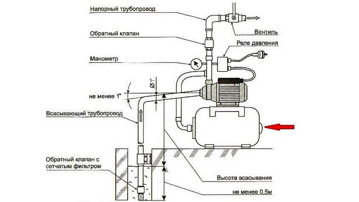
The pressure switch for the pump is recommended to be mounted at the outlet of the accumulator. This is the place where turbulence and stream jumps are leveled. Some models can not operate at temperatures below 4 degrees or at a moisture level above 70%, so it is necessary to check it in the technical passport.
It is mandatory for the relay to have such elements before it in the system:
- Mechanical cleaning filter;
- Pump and pipeline;
- Vent input;
- Fine filter;
- Check valve;
- Exit to the drainage of the water supply.
To date, some models have inclusions in the design of the choke, filters and check valve. Therefore, for these devices it is possible to install in a unit with a pump. If the water pressure switch for the pump has a water protection circuit, it can be mounted even in the well.
Attention! All the nuances for choosing a location for relays depend on the model and the technical requirements for it.
Work parameters

Before installing the relay, you must already have the pump and accumulator installed, and also determine the necessary settings for operation:
- Indication of the maximum possible pressure for installation;
- The minimum reading required to turn off;
- The amount of pressure in the air chamber of the accumulator.
Important! To learn the minimum pressure, you can add 0.2 atmospheres to the pressure of the air chamber of the water accumulator. If this is not the case, then the system is worn out more quickly.
The electronic pressure switch can be of the following types:
- Power, which organizes the inclusion of power contacts on the pumping unit;
- Control, which gives a signal to the power control module.
Attention! It is necessary to immediately determine the maximum switching power for this model of the relay and adjust it.
Design Features and Customization
This mechanism is a fairly simple design, which consists of a device, a choke and a group of terminals for connection to electrical cables. Adjustment of pressure data is carried out by springs, which have threaded recorders.
There is such a regularity that the more force is applied to the springs, the higher the pressure is needed to activate the relay. The principle is this: when we compress the springs, we increase the value of our pressure.
Attention! The setting of the pressure switch according to the standard has this value: the minimum value is 1.5 bar and the maximum value is 3 bar.
Despite this, from time to time the mechanism needs adjustment.
Relay adjustment

Adjusting this device is a very important process that allows you to return the device to a full and optimal production. There are some nuances of this process:
- In most cases, the relay is equipped with two springs of different diameters;
- Large diameter spring is designed to control and stabilize the levels of indicators;
- Setting a spring with a smaller diameter - determine the differential of the levels;
- The clamp of a large spring increases the highest and lowest mark of magnitude;
- The clamp of a small spring adds to the maximum index the superiority over the minimum.
Connecting the relay to the system
To connect the relay to the system, this instruction can help you. Order of sequential actions:
- The process of installation of equipment is carried out according to the scheme or the adjacent instruction;
- We install the tee in the right place on the pipeline, attach it to the relay device;
- Using FUM tape or hemp rope, we seal the threaded joint;
Important! In the standard set, only nuts go to the relay, therefore it is necessary to independently purchase a connection similar to an American, or with their own hands to rotate the device on a tee.
- Using a cable with a suitable cross-section for power, we connect the electrical system;
- We establish the terminals, which must have inscriptions according to the intended purpose. If they are not, then it will not be difficult to determine by the scheme.
- If there is a ground terminal, the grounding cable must be installed.

To select the most the best option for your pump, you need to adhere to such small recommendations:
- Choose a device that is designed for domestic work. The pressure level should not exceed 4 bars, since the standard optimum range varies between 1.4 and 2.8 bar.
- It should be noted that the higher the differential between the maximum and minimum level, the greater the amount of water in the tank and thereby reduce the frequency of the pump's activation.
- Give preference to models of well-known brands, since there are a lot of fakes, which can negatively affect the functionality of the entire system.
- The installation of a pressure gauge on the pipeline will be a positive thing - this will enable you to monitor the level of pressure and thus protect the system from unexpected situations.
Now you know all the working nuances of the relay device and the operating rules!
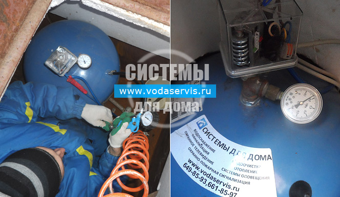
Quality water pressure sensors in the private water supply system are simply necessary. Thanks to these small devices, the equipment operates in a suitable mode and less often breaks down. Periodically, the pressure switch must be replaced. And folk craftsmen who decided to assemble the pump station on their own, rather than buying a ready-made unit, will have to install the sensor with their own hands. It is important to properly connect the device, and then properly configure it. In this material, we will describe in detail how to do this.
How does the water pressure sensor work?
The pressure switch is a small device that controls the operation pumping station. It measures the water pressure in the system and, based on the received data, turns the pump on or off. When the pressure in the system decreases, the relay turns on the pump and the hydraulic accumulator is filled. When the pressure reaches the maximum value specified in the instrument setting, the pump is switched off. When the amount of water decreases and the pressure reaches a minimum value, the device switches on and the cycle repeats.
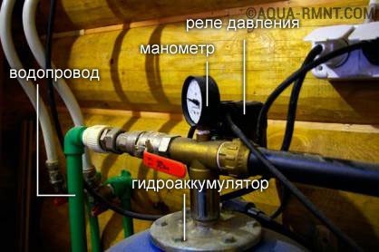
The water pressure sensor in the water supply system allows you to monitor the level of the accumulation of the accumulator and to control the on-off of the pump in automatic mode
For normal operation, the water pressure sensor in the pipeline must first be connected to the water supply system. Then the device is connected to the power supply. After that, the relay needs to be set up, and only then it can be considered ready for operation. An overview of several models of pressure switches is presented in the following video review:
How to connect the sensor to the water supply?
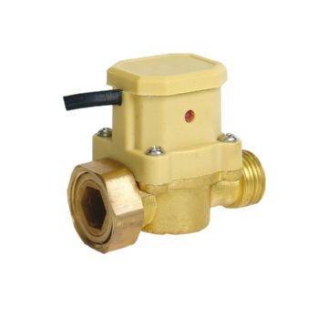
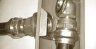
To connect the device to the water supply system, a special nut is provided on it. It is rigidly fixed to the relay, therefore at installation it is necessary to rotate all device clockwise. On modern pumps, there is usually a specially designed place for mounting the pressure switch. If such a nest is not provided, you should use an inch brass tee, called in the people "herringbone". This convenient part allows you to connect to the water main and pressure switch, and a pressure gauge, and a hydraulic accumulator.
A special plunger for the water pressure sensor allows you to connect all the necessary elements to the water supply system: a relay, a tank and a manometer
Before starting the installation, the location of the differential pressure sensor sockets should be examined. Sometimes the pipes or the elements of the pump itself interfere with the normal installation of the relay. In this case, you should take care of the part that will fulfill the role of the "extension".

Not always the input for water on the relay has standard diameter a quarter of an inch, especially if you are not using a household, but a professional model. A suitable brass adapter is required to properly install the device.
When connecting the pressure switch to the water main, it is necessary to tighten the threaded connection. To do this, you can use flax or a special thread Tangit Unilok. It is not cheap, but according to experts, this material is more convenient to use, it provides a more reliable result. For beginners, it is not always possible to make a reliable thread seal on the first attempt.
When working with a sealing thread, one should adhere to a number of recommendations:
- before starting the thread, it is necessary to turn the thread to itself;
- the winding is produced not from the end, but to the end clockwise;
- start winding should be from about the part of the thread to which the relay will be screwed, i.e. the sealing thread must be on that part of the thread which will then be hidden under the mounting nut of the pressure switch;
- the first seal loop must be firmly fixed;
- then the thread is gently wound in such a way that it is placed evenly and does not fall into the grooves;
- the amount of seal should be sufficient to prevent leaks, but not too much, otherwise the nut will not wind or the thread will crumble so that leaks will still appear.
After the sealing thread is laid, it is possible to screw the relay. This should be done manually, slowly. When there is resistance, you need to equip with a wrench. If the process comes with some resistance, and the sealing thread remains flat and does not form loops, then the seal is done correctly. If the thread becomes entangled, forms loops, gets out, it is necessary to remove the relay and put the sealant again. If at winding only one or two small loops are formed, and in general the tangite lies exactly, this is an allowable blemish, you do not need to alter the work.
Connecting the device to the power supply
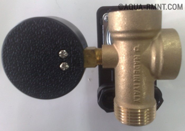
The next stage of installation of the water pressure sensor is the connection of the device to the mains. First, you need to find two groups of contacts on the relay, which are normally closed, but when the maximum pressure is reached, they must open. Usually the location of these contacts is indicated in the instructions to the pressure switch. If there is no instruction, any electrician will be able to determine.

The photo clearly shows the location of the contact pairs to which the power is supplied. When the maximum pressure is reached, the contacts are opened and the pump is switched off
Note! To connect the relay to the mains, it is recommended to use a cable whose characteristics correspond to the power of the pump.
Now it is necessary to screw the conductors of the wire to the free contacts of each pair. Do not connect the contacts of one pair in this way, as this will result in a short circuit. The ground wire is connected to a special screw on the relay housing. This screw is indicated by the corresponding symbol.
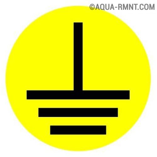
This symbol denotes a ground contact. The lack of grounding of the appliance is a dangerous violation of safety precautions, which can lead to an accident and even injuries
Then the pressure switch must be connected to the pump. To do this, use a piece of wire of suitable length. One end of his veins are screwed to the free contacts of the relay, the second - to the contacts of the pump. It is recommended to observe the color of the cores. The grounding of the relay and the pump can also be connected, although this is not necessary.
After that, you need to check the operation of the system. If, as the water is withdrawn, the pressure on the manometer increases, when the maximum is reached, the pump is turned off, and as pressure drops, the pressure is lowered, the relay setting is correct.
How to set up the unit correctly?
Normally, the settings set by the manufacturer are sufficient for the system to work properly. For example, the factory settings of the model GDMlex-RDM-5 are 1.4-2.8. If, for some reason, they need to be changed, all manipulations should be done very carefully, so as not to spoil the device with inept handling.
Before setting the relay, you must:
- Disconnect the power supply to the pump.
- Drain all the water from the system (the needle of the pressure gauge will reach zero).
- Turn on the pump and fill the system with water.
- Wait for the pump to automatically shut off and lock the shutdown pressure.
- Release the water, wait for the pump to turn on automatically, and fix the on-off pressure.
Attention! Before setting the pressure switch, check the pressure in the accumulator. This value should be 0.2 less than the minimum value set on the pressure switch. In addition, before starting the relay setup, it is recommended to clean the filters available in the system.
To adjust the water pressure sensor used two springs - large and small. With the help of a large spring set the maximum value of water pressure in the system. For this, the spring is twisted. A small spring regulates not the minimum pressure value, but the difference between the minimum and maximum. If the preset value seems too small, this spring should also be tightened until a suitable value is reached. Do not twist the spring itself, but the nut that holds it. When tightening this nut, the spring is shortened, and when unscrewed, it straightens.
The system of automation of the water supply system is responsible for ensuring that the tap water flows under pressure.
Principle of operation
The system consists of the following components: a pump, a hydraulic accumulator and a pressure switch. The downhole pump pumps water through the pipeline to the hydraulic accumulator. Accumulator for water supply systems is a reservoir, inside which there is a pear-shaped membrane. On the one hand water, and with the other compressed air. Increasing in size, the membrane compresses the air. You open the tap, the water goes under pressure, and the pressure in the system decreases - as soon as the pressure falls below the critical pressure, which is set by adjustments, the relay turns on the pump and it again pumps the water into the tank. The pressure in it increases, when the maximum is reached (set by adjustments), the relay reacts again and turns off the pump - in the water supply system a country house again a constant pressure and you get water under pressure.
Thus, the pressure switch is designed to control the electric pump. At the same time, the life of the pump increases.
Design of the water pressure switch
This is a block, inside of which springs are arranged, regulated by special nuts. The water pressure in the water supply system is transferred by means of a membrane or bellows. These transmitters either override the spring resistance (when setting the maximum pressure value), or weaken the spring (at minimum pressure). Springs close or open the electrical contacts inside the relay. When the minimum set pressure value is reached (normally it is less than 1 bar), the relay contacts are closed, and the electric current passes to the pump by which the relay controls. Water comes from the well to the tank. As soon as the pressure reaches the set maximum, the spring opens the contact, the electric circuit of the pump breaks, and it stops pumping water.
The standard relay can be adjusted in the range from 1 to 8 bar.
Normally, all pressure switches have a factory setting of the pressure values - the relay is triggered to turn the pump on when reaching 1.4 bar, and on the shutdown - 2.8 bar.
When choosing a manufacturer, pay attention to the tuning range, the working environment (after all, the relay can be used not only for water), additional functions (some relays, in addition to starting the pump by pressure, carry out its start-up along the flow path, and also protect it from "dry running"). Naturally, the more functions of such a relay, the more expensive it will be. The operating pressure range also affects the price.
Pressure switch Gileks, Danfoss, Italtecnica
So, the pressure switch Danfoss (Denmark) with a range of 0.2 - 8 bar will cost about 3000 rubles. The pressure switch Grundfos (Germany) with similar settings will cost already 4,5 thousand rubles. The pressure switch of the Italian firm Italtecnica with standard values costs 500 rubles. The relay of the Russian firm "Dzhileks" similar to Italian products is cheaper by 200 rubles. Thus, the domestic producer is cheaper, and in terms of its characteristics it is not inferior to Western analogues. But, it is desirable, that all pumping equipment was produced by one manufacturer, that is, if you have grundfos well pump , then the pressure switch is best applied in accordance with the recommendations of this manufacturer.

 Well Water Equipment
Detailed review with photos of the necessary components for the arrangement of its own autonomous water supply system to the private house.
When operating a pumping station that supplies water vacation home, the equipment usually includes a pressure sensor.
This device is mandatory in the event that the pumping station can operate in automatic mode, that is, turn the pump on and off without the presence of a person.
Appointment
The pressure sensor (sometimes called the pressure switch) is used in the pumping station of the water supply system at home to automatically maintain the required pressure in the water supply.
- When opening the cranes and reducing the amount of water in the accumulator, the pressure in the water pipe decreases.
- When the minimum permissible pressure in the sensor is reached, the contacts close.
- As a result, a pump installed in the well starts to pump water.
- The pressure of water begins to increase.
- When the maximum permissible pressure in the relay is reached, the contacts are opened and the pump is switched off.
- Then the process repeats.
So in a waterpipe the necessary pressure is maintained.
Pressure sensor device
As a pressure sensor in the house water supply system, both mechanical and electronic sensors can be used.
In the mechanical sensor, the membrane reacting to water pressure switches off and connects to electrical network pump. In the electronic sensor, the deformation of the membrane is converted into a control electric signal, which is amplified, digitized and enters the automatic control system. Due to its simplicity and relative cheapness, sensors with a mechanical principle of operation are more common.
The design of this sensor includes a connection for water connection, a diaphragm, a contact group, two springs, with which the minimum and maximum pressure of the sensor is set.
Springs have different diameters. In this case, a large-diameter spring regulates the pressure levels in the water pipe, and a small-diameter spring determines the pressure difference between the two control thresholds.
When adjusting to increase the pressure levels of operation, it is necessary to compress the spring of large diameter. This is done by twisting a special nut. When the small spring is clamped, the pressure difference between the operating levels increases.
Sensor Models
The table shows the main parameters of some pressure sensors and their prices. In this case, the first three sensors relate to mechanical sensors, and the last two sensors to electronic pressure sensors.
The table shows that the prices for pressure sensors produced by the German company Tival, several times higher than the domestic sensor RDM-5 and the sensor Italian company Italtechnika PM5.
The high price is explained by the company's brand and the fact that expensive sensors can have additional functions.
For example, the FF-4 relay protects the pump from a "dry" operating mode, that is, a mode where the water level is too low and the running pump can fail due to lack of cooling. In addition, for such a sensor there is a large margin for adjusting the pressure limits, which makes it more versatile. The adjustment of the FF-4 sensor is facilitated by the fact that the sensor has a special scale for tuning, and thanks to the transparent cover you can easily see the settings parameters.
Electronic Water Sensors
The electronic sensor A-10 of the German company Wika is a device designed for active measurement and conversion of pressure into an analog electrical signal (the output signal is a current of 4-20 mA or a voltage of 0 to 10 V). This signal can be fed for further processing to a programmable controller or automatic water system control device.
The KIT 02 sensor of the Spanish company ESPA is an electronic unit designed to operate the pumps. The KIT 02 sensor ensures the operation of pumps with a current consumption of no more than 10 A. When using a more powerful pump, an additional magnetic starter must be used.
Advantages of electronic sensors of this type:
- ensuring a stable pressure in the intervals between on and off the pump;
- reduction in the number of pump starts. Due to the reduced number of pump starts, the negative
- the effect on the windings of the pump motor of large inrush currents, which increases its service life;
- providing electronic protection of the pump from "dry" running, working with a closed valve;
- extinction of water hammers.
Disadvantages of electronic pressure sensors:
- the need for a separate unit for power electronics;
- high price.
Connecting the pressure sensor
This is due to the fact that in these parts of the water pipe, when the pump is turned on, smaller pressure jumps occur. In addition, the operation of many sensors is possible only indoors. To connect these sensors are used special tees, which allow you to connect the main hydraulic accumulator, pressure sensor and pressure gauge.
Modern pumps, as a rule, have special fittings for connection of pressure sensors. Therefore, sensors made in a waterproof version can be installed in the caisson of the water supply system or even in the well.
After connecting the pressure sensor, the corresponding contact groups are connected to the pump and the sensor ground. When connecting electrical cables it is necessary to take into account the power of the pump. For example, for a pump with a power of 2 kW electrical cables must have a section of at least 2 mm².
After this, the system can be connected to the network and checked for proper operation of the pump.
If, when it is turned on, the pressure gauge indicates an increase in the water pressure in the water supply, the system is operable.
Sensor adjustment
Normally, the factory settings of pressure levels are sufficient for the correct operation of the water pressure control system. For example, for the Gillex RDM-5 sensor, the minimum and maximum threshold for the sensor is 1.4 and 2.8 bar, respectively. But in some cases, an additional sensor adjustment is required.
Before adjusting the sensor, first check the pressure in the accumulator. Thus it is necessary:
- Disconnect the network;
- Drain the water;
- Remove the side cover of the gyroaccumulator and the car pump to measure the pressure;
- If the pressure is less than 1.5 atm, then it must be increased by means of a pump;
- If the pressure is too high, then it must be reduced by pressing the nipple.
For adjustment it is necessary to perform the following operations: 
- Disconnect the power from the network;
- Drain the water from the system. Check the zero pressure on the manometer;
- Turn on the pump to fill the system with water;
- Fix the moment when the pump is switched off and note the pressure when the pump is switched off;
- Release the water, fixing the pump on and pressure at this switch-on;
- Disconnect the power supply and remove the sensor cover;
- Loosen the nut of the small spring;
- Install the desired minimum operating pressure with the large spring nut. In this case, the compression of the spring increases this pressure, and its weakening reduces the pressure.
- Pump water into the system.
- Repeat step 5. If the pump start pressure does not match the set pressure, repeat step 8.
- Adjust the maximum threshold with a small spring. Compression of this spring increases the difference between the thresholds of operation, and the attenuation reduces this difference.
- Turn the pump on and lock the pump off and pressure at this point. If the cut-off pressure of the pump differs from the desired one, repeat the maximum pressure adjustment (step 11) until its value is equal to the desired threshold.
By this adjustment, for example, it is possible to increase the difference in operating pressure, which is factory-set. This reduces the number of pump starts. However, on the other hand, the pressure drop in the water supply network will increase. And this can affect the reliability of the elements of the system.
In addition, if you set the thresholds of the sensor, you must take into account the capabilities of the pump. For example, in order to compensate for losses in a water pipe, it is desirable to have an excess of the pressure created by the pump of 0.5 bar. Otherwise, the pump will work with overload, which will affect its reliability. Experts recommend even when working with a sensor having factory settings, to check the pressure in the water pipe every year and, if necessary, to adjust and adjust the pressure sensor.
conclusions
- To provide automatic work pumping station requires the use of a pressure sensor.
- Pressure sensors are mechanical and electronic.
- If necessary, you can independently adjust and adjust the sensor. When you configure the sensor yourself, you must take into account the features of the water supply network.
Automatic operation of the pumping station is not possible without using a water pressure switch for the pump. This device rigidly sets the limits of the permissible value of pressure in the system and the head that the consumer uses. As a result, the outlet always has a stabilized water pressure, and the pump only works when there is a need for water.
The pressure switches can be mechanical and electronic. Distribution is precisely mechanical devices due to its simplicity, reliability and reliability. Their setting requires minimum effort and can be performed at the connection point.
The main task of the pressure switch is to control the pump. The feed line of the pump is switched through it. Switching on and off depends on the pressure in the pipes. For an automatic pumping station consisting of a pump and a storage tank, the workflow is as follows:
- The nominal system pressure is set, as well as the permissible limits for the minimum and maximum pressure.
- When the minimum threshold is overcome, the pump turns on and pumps the water to the consumer and to the storage tank.
- If the upper threshold is exceeded, the pump is switched off.
The pressure switch determines the permissible limits for the minimum and maximum pressures and turns on the pump according to the above algorithm.
By way of controlling the pump, the power and signal relays are distinguished. The first directly controls the power supply of the pump, and when selecting, you should be guided by the maximum permissible current. The second, signal, commutes or generates a low-voltage signal for the control unit.
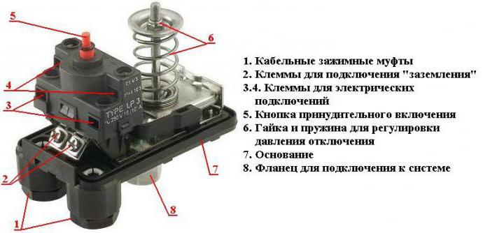
The device is structurally divided into three parts:
- hydraulic block, diaphragm;
- detection unit, spring set-up unit;
- power or signal relay.
The hydraulic unit of a simple mechanical pressure switch is a sealed chamber with a membrane inside it. On one side of the camera there is a connection for connection to water pipe. Water enters one part of the chamber and presses against the membrane; on the other hand, a movable rod is connected to it, coming out from the other side of the chamber.
The detection unit determines the conditions of operation of the relay, it responds to the pressure change in the system. To the rod coming out of the sensor chamber, connect a plate-lever to control the power relay. Depending on the pressure applied to the membrane, the relay closes or opens the contacts. In order to balance the membrane and determine the maximum permissible level of operation, a spring unit is attached to the stem, which exerts a pressure comparable to that of the water pressure. The tension of the springs is regulated by means of nuts and clamping washers.
A power or signal relay is a group of plug-in terminals and terminals for connecting a power line to the pump or signal line for the control unit.
Relay device layout
The key element of the device is the spring control unit. If you uncover any mechanical relay, it reveals one large spring and one small one. They determine the response levels.
A large spring exerts the main pressure on the sensor rod, determining the maximum allowable division, at which increase the relay contacts are opened and the pump is switched off.
A smaller spring determines the differential pressure, the difference between the upper and lower threshold.
For both springs there are adjusting nuts that control the degree of tension. It is important to understand the purpose of the springs correctly.
If you change the compression ratio of a large spring, then both thresholds of the relay will move to one side or the other.
If you act on a smaller spring, and do not touch a larger one, only the lower threshold of operation changes.
Connection diagram
The pressure switch is activated after the pump and immediately before entering the accumulation tank. To protect the sensor from contamination, the effects of pressure surges as a result of starting and stopping the pump, it must already be installed in front of it:
- coarse filter;
- pump;
- shut-off valve;
- check valve;
- fine filter;
- draining to the sewage system through the break valve.

Wiring diagram of relay for pump station
For the normal operation of the automatic pumping station, the storage tank is set to a maximum pressure higher than the nominal nominal for the water supply by about 0.5-1 bar. The upper threshold of the relay is set to 0.2-0.3 bar below the maximum. The differential specifies the bandwidth of the permissible pressure and can correspond to a value of up to 2 bar.
The smaller the differential, the difference between the upper and lower thresholds, the more often the pump starts, but more stable head on the consumer side.
The higher the differential, the less the pump turns on, but significant pressure changes on the consumer side are possible.
To the terminals of the relay, connect the supply wires from the distribution board and the power wires of the pump in accordance with the manufacturer's instructions, being guided by the signature and the color marking of the wire. In the presence of a terminal marked "earth", a cable from the common ground is necessarily connected.
Adjustment
Relay before use with most pumping stations does not even require additional configuration. If you select a relay with the appropriate maximum allowable threshold, then the settings from the factory already have the optimum values. For pumping stations designed to supply water in a private house, this is most often a shutdown at 2.5 (3) bar and switch-on at 1.5 (1.8) bar.
However, to specify specific settings, when the factory settings do not suit, it is necessary to perform the initial setting of the equipment. To do this, it is mandatory to install a pressure gauge connected to the same five-pin choke as the relay. It is assumed that the whole system is already assembled and ready for the first start, if necessary, water is already collected to the non-return valve, excluding the idling of the pump, and in the storage tank there is already a minimum volume of water.
Before setting up, you should select:
- the maximum allowable pressure in the system;
- minimum pressure;
- air chamber pressure of the accumulator with the water running down.
Before adjusting, it is necessary to remove the sensor cover and prepare the appropriate socket wrench for adjusting nuts.
The procedure is as follows:
- Turn on the pump to fill the tank.
- When the manometer reading is reached to the required maximum value, for example 3 atm, manually turn off the pump. If the relay has worked before the time, then turn the main spring nut clockwise one or two turns and repeat this step.
- At the steady pressure in the system at the maximum level, turn the main spring nut counterclockwise until the relay trips. This sets the upper threshold.
- Open any tap in the house and wait until the gauge reading reaches the required lower threshold. It is set to 10% more than the pressure of the air bag of the accumulator.
- If during the water drain the relay has already tripped, then turn the nut of the smaller spring counterclockwise, if the relay does not work, then turn clockwise until a click of the relay triggers.
- Switch on the pump and check the correctness of the upper threshold setting, if it is too high or too low, finally adjust by tightening or loosening the nut half a turn according to clause 3.
- Discharge the water through the tap until the lower threshold is triggered and the pump will turn on again. Check the required value and, if there are deviations, repeat the setting in step 5.
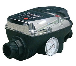
Electronic relay
Along with a mechanical pressure switch, electronic relays are also used. More often they are a full-fledged pump control unit, including a softstarter and a protective trigger and, accordingly, setting the upper and lower threshold in operation.
For adjustment, use the adjusting bolts located on the body of the device. For convenience, around the bolts, marking and marking are often applied for orientation at specified pressures.
Special advantages of electronic relays do not give, however they have smaller dimensions and do not produce any extraneous sounds when triggered, although this is not actual for installation directly near the pump.