Build electrical cabinets. Electric cabinet with electrical connection in the door
Electrical wiring diagrams are often used to connect various electrical equipment, electrical equipment and machinery. They allow connection of separately located complete devices. Electrical circuits for each structure (control station switchboard, cabinet, console) are carried out on a separate sheet.
Included in the set of step-down transformers, resistance boxes, magnetic amplifiers are installed at the rear of the shield on separate racks and refer to the wiring diagram of the shield. When the shield is made of several parts, the mounting block is displayed on a separate sheet. The block length must be within 4 meters, which corresponds to the parameters of the platform for transportation.
When two adjacent panels are included in different structural units, the electrical connections are made during installation. The manufacturer of electrical flaps can not perform such connections, since the shield equipment is transported in separate blocks.
Standard or special equipment control cabinet is a complex construction in which only an experienced specialist is able to understand. He also has to deal with the construction of an electrical scheme for the distribution of energy at the site, the choice of suitable equipment. Every competent person knows that electrical circuits for various purposes must be separated by free clamps. For example, electrical signaling circuits are separated with electric control circuits of electric drives.
Separation of circuits with different voltages is a mandatory requirement. Clamps of chains of one appointment are typed in succession. After a row, follow the clips of chains of another purpose. To ensure easy wiring of the cable, it should be possible to connect the wire to the electrical power contacts of the equipment in the shields.
There are several ways to perform electrical wiring. Depending on the purpose of the electrical device and the method of installation, the electrical circuits are constructed in different ways.
The electrical diagram of the control cabinet shows the direction of the flow of wires that go to the rail of the clamps installed on the side wall. All the clamps have serial numbers. To reduce the number of electrical drawings, the wires are often shown on the diagrams.
To ensure high reliability in the operation and maintenance of electrical equipment, high-quality relay-contact equipment is used. The qualitative construction of the electrical circuit allows:
- ensure trouble-free operation of equipment;
- facilitate the installation of electrical appliances;
- minimize the likelihood of electric shock.
The electrical cabinet contains an electrical box, a locking door and a hinge unit. On the box and door, electrical wires are laid, each of which extends from an electrical component located inside the electrical equipment compartment formed by the box to the outside of said compartment for connection to a corresponding electrical connector. For this purpose, according to the invention, electric wires are passed through a hinge assembly. The latter is made in the form of an electrical connector and is intended for connection electrical wires, coming from the electrical cabinet, and electrical wires placed on the cabinet door. The connecting means comprise drilled holes for passage through which bundles of electric wires are laid. Each hole is formed in the longitudinal direction relative to the axis of the wire routing through the hinge assembly. The axis of the gasket is perpendicular to the axis of rotation of the hinge unit. The technical result is to reduce the space occupied by electrical wires. 2 N. and 15 z.p. 4-yl, 4 yl.
Drawings to the patent of the Russian Federation 2369951


Technical Field
The present invention relates to an electrical cabinet with an electrical connection system made in a door.
The invention can be applied in any technical field where such electrical cabinets are equipped with electrical components. In particular, the invention can be applied in the field of aviation. The invention can also be used for the equipment of administrative buildings.
Prior Art
The electrical cabinet contains an electrical box, a locking door and a mechanical hinge. The box forms a compartment for electrical equipment with an opening for access from the outside. The door interacts with the box through the hinge, rotating at least between the closed position and the open position. The closed position of the door is the position of the door, in which the door covers the area bounded by the opening of the instrument compartment. The open position of the door is the position of the door, in which the area bounded by the opening of the compartment is not covered by the door. The door rotates relative to the box with a hinge.
The hinge comprises at least one first connecting means, at least one second connecting means and means for hinging the first connecting means with the second coupling means. The first connecting means is attached to the box, and the second connecting means is attached to the door. The hinging means can be formed by a fastening rod disposed along the axis of rotation of the hinge. The axis of rotation of the hinge is the axis around which the second connecting means is hingedly attached to the first connecting means, which allows the door to rotate relative to the electrical box.
In a simple embodiment, the connecting means comprise simple articulated links through which the rod passes.
BRIEF SUMMARY OF THE INVENTION
An object of the present invention is to reduce the space occupied by electrical cables laid inside the electrical equipment compartment formed in the cabinet.
According to the present invention, the box contains electrical components that must be connected by electrical cables to other electrical components, for example, in a large number mounted on the door. Fastening components on the door allows, on the one hand, to saturate the cabinet with a large number of components and, on the other hand, to maintain very good accessibility to all components. It is enough to open the cabinet door to gain access to the components contained in the compartment and to the components attached to the door.
The components fixed in the box or on the door are often arranged in the form of a battery. In the field of aviation, they can be, for example, electrical relays or electrical indicators serving the electrical equipment of an aircraft. For example, such control panel equipment is located near each seat of the aircraft. In the field of building equipment, such components may be electrical relays or switches associated with building lamps, in particular with security warning lights.
Thus, the components are fixed in the box and on the door. They are connected by electrical wires. Each of these wires is attached at one end to the component inside the compartment and must be connected to the other component on the door by its other end. If necessary, such a connection at the other end may contain a connector.
The electrical connections are installed in series. Typically, the installer starts connecting with the components located in the form of a battery. For example, it connects the wire to each of the components. Then he collects the connected wires into bundles. Then these bundles are properly connected so that the connected wires do not turn into tangled bundles. Thus, sometimes several beams are formed, consisting of three or six dozen wires.
These beams must connect the components in the door with the components in the box. Since the door is movable, i.e. open, the bundles must have some flexibility so as not to interfere with the opening or closing of the door. In practice, the beams formed are U-shaped. Both branches of U are parallel to the hinge axis. When the door is opened or closed, both branches of U produce a movement of rotation around themselves, while moving away from each other or approaching each other. Rotation is possible due to the fact that the number of wires in each beam does not exceed the allowable limit. When closing, the approach is due to the deepening of U: the branches of U are elongated and thus produce the necessary length clearance. In the reverse situation, when opening, both branches move away from each other, and the bottom U rises. It is also possible to provide an inverted U-shape, in which the branches are directed downward.
The presence of U-shaped beams leads to the filling of space in the instrument compartment of such an electrical cabinet. This can make the compartment ventilation difficult for the normal electrical operation of the electrical components inside the compartment of the electrical cabinet. Indeed, the resulting density of cables can interfere with the removal of heat, which, as a rule, is a necessary condition for the normal operation of electrical components.
To solve this problem, the invention provides for an improvement in the laying of cables from the cabinet compartment towards the cabinet door. According to the invention, electric cables are passed through a hinge. According to the invention, it is also provided that the hinge is transformed into an electrical connector so as to connect, on the one hand, electrical wires running from the box and, on the other hand, wires coming from the door. In addition, the joint-hinge according to the present invention allows the components contained in the box or outside the box to be connected to components located on the door inside or outside this box.
Thus, the advantage of the proposed electrical cabinet is the much simpler laying of electrical cables in the compartment for electrical equipment.
Another advantage of such a cabinet in accordance with the present invention is the gain in time when installing the cables in the compartment.
Another advantage is associated with the problems arising when the cables are rubbed together, with the box or with the door during the interaction of the door with the box. This reduction in friction reduces the risk of rupture or premature wear of electrical wires.
Another advantage of the present invention is the optimization of the location of electrical cables in the cabinet compartment, which makes the installation of electrical equipment in such a cabinet easier and more reliable in terms of safety.
Thus, the subject of the present invention is an electrical cabinet comprising:
the electric box, which has inside the compartment for electrical equipment,
the locking door of said compartment,
the hinge formed by the first connecting means and the second coupling means, the first means being fixed to the box and the second means being fixed to the door, the first means and the second means being pivotally connected to each other about the hinge rotation axis,
at least one set of electrical components mounted on the door and / or inside the compartment, and
electrical wires connected to electrical components,
the cabinet is characterized in that the connecting means comprise a through hole through which the electrical wires pass.
Brief Description of the Drawings
The present invention will be more clearly understood from the following description with reference to the accompanying drawings, which are presented as a non-limiting example of the invention, in which:
1 is a general view of an electrical cabinet according to the invention;
FIG. 2 is a longitudinal sectional view of an electrical cabinet at the location where the hinge is located, according to the invention; FIG.
FIG. 3 is a perspective view of the connecting means according to the invention; FIG.
FIG. 4 is a perspective view of the hinge according to the invention. FIG.
Description of preferred embodiments of the invention
The electrical cabinet 1 (FIG. 1) according to the present invention can be a relay cabinet, a switch cabinet, which are used in the field of aviation, as well as for administrative buildings.
The cabinet 1 is generally in the form of a parallelepiped. Cabinet 1 contains a box 2, a locking door 3 and a hinge unit 4.
From the inside, the box 2 forms a compartment 11 for electrical equipment. The box 2 is bounded by the rear partition 6, the upper partition 7, the lower partition 8 and the two side partitions 9, 10. The rear partition 6, the upper partition 7, the lower partition 8 and the two side partitions 9, 10 define the compartment 11. In this compartment there are electrical components (not shown), electrical wires 5, etc. The equipment compartment 11 communicates with the outside through the opening 12.
The door 3 is located parallel to the rear partition 6 and is installed on the edges of the bottom 8, the top 7 and the side 9, 10 partitions. The door 3 can move between the closed position and the open position relative to the box 2. The closed position of the door 3 is the position of the door 3 relative to the box 2 in which the area bounded by the opening 12 of the compartment is covered by the door 3. The open position of the door 3 is the position of the door 3 with respect to of the box 2 in which the area defined by the opening 12 of the compartment is not covered by the door 3. FIG. 1 shows the closed position of the door. The door 3 is rotated between the closed position and the open position on the hinge 4.
The hinge 4 comprises at least one first connecting means 13 and at least one second coupling means 14. The first connecting means 13 is fixed to the box 2 and the second connecting means 14 is fixed to the door 3. The first connecting means and the second connecting means the means are connected to each other by means of a hinge joint (not shown). The means of articulation can be a screw and a nut. The hinging means may also be a fastening rod passing through the first means 13 and through the second means 14 while keeping the first means on the second means relative to the hinge rotation axis 16 and vice versa. The fixing rod may be disposed along an axis coinciding with the axis of rotation 16 of the hinge 4. The rotation axis 16 is an axis around which the door 3 rotates relative to the box 2.
The cabinet 1 also contains electrical components and electrical wires 5. Electrical components are installed inside the compartment 11 along at least one of the partitions 6, 7, 8, 9 or 10 of the box 2 and / or along the door 3 on the side of the door opposite the compartment 11. The electrical components can also be installed outside the compartment 11 on the box and / or on the door. Several electrical wires, such as wires 5, can be grouped, forming electrical cable or bundles of electrical fibers. Wires are connected to electrical components.
According to the invention, the connecting means comprise through-drilled holes 18, 19 through which electrical wires pass. The first connecting means 13 and the second coupling means 14 each include through holes 18 and 19, respectively. The connecting means prevents the electric wires 2 from being forcedly bent by pressing against the door 3 and the box 2 while turning the door towards the box and the door 3 entering the closed position.
2 shows a first connecting means or a second connecting means. Such a connecting means is made in the form of a block of material in the form of a parallelepiped. In a preferred embodiment of the present invention, the first connecting means 13 and the second coupling means 14 are made in the form of identical parts. Such a connecting means can be made by injection molding parts of an insulating material, such as plastic. The advantage of the process of molding plastic is that the process is relatively inexpensive. The coupling means can also be performed by machining plastics or metallized material.
The through hole 18 (19) is formed in the block in the longitudinal direction with respect to the axis 29 of the electrical wires in the hinge 4. This pivot axis 29 is an axis perpendicular to the pivot 16. Thus, the opening 18 (19) defines a wall 22 formed by the connecting means. The opening 18 (19) allows the electric wires to be guided by the wall 22 parallel to the plane formed by the bracket on which the connecting means is fixed. The bracket can be made in the door 3 or in one of the partitions 6, 7, 8, 9, 10 forming the box 2.
In the longitudinal direction relative to the gasket axis 29 and on either side of the axis parallel to the rotation axis 16, the connecting means 13, 14 comprises a first end 25 and a second end 26. The first end 25 is continued by the first post 27 and the second post 28, the second stand is made substantially perpendicular to the axis of rotation 16 of the hinge 4 and longitudinally relative to the axis 29 of the wiring of the electrical wires through the connecting means. Each of the legs 27 and 28 is also in a plane substantially perpendicular to the axis of rotation 16. The connecting means is designed in such a way that the through hole forms a rectilinear channel along the shim axis 29, extended by the space delimited by the first pillar and the second pillar. The first post 27 and the second post 28 comprise an end 30 and an end 31, respectively. At each end, a through hole 32, 33, respectively, through which the means for the hinged connection passes. Thus, the opening of the first pillar is above the other opening of the second pillar in the longitudinal direction relative to the pivot 16.
The first pillar 27 and the second pillar 28 each include an outer side 34, 35 and an inner side 36, 37. Each of the inner sides 36 and 37 defines a portion of the through hole 18, 19, while each of the outer sides is opposite to the respective inner sides. In the example of FIG. 3, each of the inner sides is in a plane parallel to the axis of the gasket 29 and each of the outer sides is in a plane having a slight inclination with respect to the axis 29 of the gasket and at the same time is directed towards the axis 29 of the gasket. These forms of racks allow you to reduce weight and reduce the cost of the final hinge.
The end 30 of the first pillar 27 and the end 31 of the second pillar 28 comprise a first shoulder 38 and a second shoulder 39, respectively (FIG. 3). The first shoulder 38 and the second shoulder 39 are formed on the outer side 34 of the first pillar 27 and on the inner side 37 of the second pillar 28, respectively. The first shoulder 38 and the second shoulder 39 can also be formed on the inner side 36 of the first pillar 27 and on the outside 35 of the second pillar, respectively. The first shoulder 38 and the second shoulder 39 can also be provided on the inner side 36 of the first post 27 and on the inner side 37 of the second post 28, respectively. The first shoulder 38 and the second shoulder 39 can also be provided on the outside 34 of the first post 27 and on the outside 35 of the second post 28, respectively.
To reduce the cost of the cabinets, the first shoulder 38 and the second shoulder 39 are preferably formed on the outside 34 of the first post and on the inside 37 of the second post. In this case, only one mold can be used to make the first coupling means and the second connecting means forming the hinge in accordance with the present invention.
The first connecting means of said pair of connecting means can interact with the second coupling means of the same pair of connecting means by setting each first step 27, respectively, to each other and each second shoulder 28 also corresponding to each other. The second means is arranged with respect to the first means symmetrically with respect to the axis parallel to the rotation axis 16 and is thus rotated 180 ° about the axis 29 of the electrical wire laying. Thus, the first connecting means of this pair of connecting means, by correspondence of the mold, enters the second connecting means of the same pair and vice versa by connecting the first shoulder and the second shoulder of the first connecting means 13 to the other first shoulder and the second second shoulder of the second coupling means 14. [
The connection of the respective first steps and the respective second ledges facilitates a relatively rigid retention of the hinge along the axis of rotation of the hinge.
The cabinet 1 may comprise several pairs of connecting means. In the example of FIG. 1, the cabinet 1 comprises six pairs of connecting means. Each pair of connecting means is configured to lay a certain number of electrical wires. According to an embodiment, 66 electric wires can be passed through each pair of connecting means.
Each of the electric wires is laid along a section whose plane is perpendicular to the hinge axis 16. The electrical wires are laid in the form of tape from adjacent wires. The plane of these belts is perpendicular to the hinge plane, in this plane the wires of these bands have bends in two directions.
The electrical components can be installed inside the door opposite the compartment 11. The electrical components can also be installed outside the door.
The first means 13 and the second means 14 can be fastened respectively on the box 2 and on the door 3 by means of the screws 20 and 21.
In the example of FIG. 1, the first means 13 is fixed along the box 2 outside the compartment 11. The second means 14 is fixed to the door 3 opposite the compartment 11 along one side of the same door. In particular, the door comprises a first side 3 "and a second side 3, with the first side 3" opposite the compartment 11, while the second side 3 is opposite to the compartment. The first side 3 "of the door 3 must be in front of the compartment 11 when the door 3 is in the closed position with respect to the box.Thus, the second means 14 is intended in particular for mounting on the first side 3" of the door 3 opposite the compartment 11. However, the second means 14 can be placed on the second side 3.
When installing the first means 13 and the second means 14 according to the example shown in FIG. 1, the electric wires can be laid from inside the compartment to the outside of the compartment and vice versa. The wire extends from inside the compartment 11 to the outside of the compartment 11, while it is laid along the door 3 inside the compartment 11 on the first side 3 "and along the box 2 outside the compartment 11 on both sides of the pivot axis 16 of the hinge 4 (Figures 1 and 2). pass from the inside of the compartment 11 to the outside of the compartment 11, while it is laid along the box 2 inside the compartment 11 and along the door 3 outside the compartment 11 on the second side 3 on either side of the pivot axis 16 of the hinge 4.
According to the same example (FIG. 1), at least one of the connecting means is connected to an electrical connector 17. In the described embodiment, each of the connecting means 13 and 14 is connected to a connector, such as a connector 17. Such a connection of the connector 17 to At least, with one of the connecting means allows to reduce the length electric wire 5, necessary for internally guiding the compartment 11 from the outside of the compartment 11. In addition, this connection of the connector 17 to at least one of the connecting means prevents the electric wire 5 from being forcedly bent against the door 3 and to the box 2 during the rotation of the door on the box in the closed position of the door 3.
The connector 17 comprises at least one metal contact, for example a contact 23 intended to be connected to a corresponding electrical wire 5. In the example of FIG. 4, the connector comprises 66 metal contacts 23. Each of these contacts may be a male contact or a female contact. With the same contacts, the connector can be connected to an additional electrical connector (not shown). In an embodiment, the metal contacts of the connector form male terminals in the form of pins, the pins being designed to enter the sockets (not shown) of the additional connector forming the female contacts.
The connector 17 can be attached to the first coupling means by fitting the mold. In particular, the connector can be connected to the first means by rectangular connection in the tongue. The connector 17, the first connecting means 13 and the second coupling means 14 can be attached to the box 2 and / or to the door 3, for example, using screws.
The electrical wires are grouped, thus bending the rotation axes 16. The wires are held in a tensioned position and are grouped about the axis 16 along an axis perpendicular to the axis 16. To this end, the electrical wires of one tape are grouped and held in the form of a bag with respect to the axis 16 in the hinge by a flexible elastic binder 40. This bonding element 40 is disposed around packets of wires in the longitudinal direction relative to the axis of rotation. The linking element 40 groups the wires not only around the axis 16 but also holds the relatively tensioned wires along an axis perpendicular to the axis 16. The linking member 40 can be a flexible tape made of an elastic material. In the described embodiment, one binder element is arranged around the wire bundle for one pair of connection means.
Between the connector 17 and the first connecting means 13, the electric wire fixing means 24 can be placed. This locking means 24 is designed to hold electrical wires, each of which is connected to a corresponding metal contact 23 of the connector 17 during electrical connection or electrical disconnection of the connector 17 and an additional connector. The fixing means 24 also serves to provide a seal against the air of the electrical connection between the metal contact 23 of the connector 17 and the end of the electrical wire 5 intended to be connected to the corresponding metal contact 23.
The fixing means 24 can be made in the form of a monoblock made of a plastic material. The block 24 comprises a plurality of openings (not shown) uniformly distributed with respect to each other. Each of the holes is formed along an axis perpendicular to the axis of rotation 16 of the hinge 4 and in the longitudinal direction relative to the axis 29 of the gasket. The electrical wires can be passed to each of the respective openings of the block 24 such that the wires are held in place during electrical connection or disconnection of the electrical connector 17 and the additional electrical connector. The wires are passed through the block 24, so that in the corresponding hole the wires are engaged due to the frictional forces with the block material. Preferably, the block is made of rubber. The unit 24 serves to retain the ends of the electrical wires. The wires can be soldered to the corresponding metal contact without fear of being disconnected from the corresponding contact, in particular during the electrical disconnection of the electrical connector 17 and the additional electrical connector. The plastic material block 24 can be fastened with screws or glue to the box or door. The same unit may extend between the connecting means and the connector 17 and simultaneously into the connecting means and into the connector 17.
In the described embodiment of the present invention, the fixing means may be embodied in the form of a clamping device (not shown). This device tends to press the electrical wires located at the output of the connecting means perpendicular to the wire guide shaft 29 in the connecting means, to the box or to the door. The device also allows you to hold in place the ends of electrical wires intended for connection to the electrical connector. The clamping device may comprise at least one rigid plate and at least one screw. The first plate and the second plate can be mounted on either side of the electrical wires parallel to the plane formed by the door or box, the second plate being pressed against the door or box. The first plate and the second plate are made of a material relatively deformable by electrical wires, which facilitates holding the electrical wires between the first plate and the second plate. In this embodiment, the first plate and the second plate can be made of rubber. The first plate is approached to the door or to the box with a screw screwed into the door or into the box through the first plate and the second plate. Screwing the screw into the door or into the box leads to the approach of the first plate to the box or to the door, which helps compress the wires between the first plate and the second plate. The compression is performed in such a way as to sufficiently hold in place the electric wires and to avoid their detachment from the metal contacts on which they are fixed during the electrical disconnection of the electrical connector and the additional electrical connector.
The wires are compressed, locally deforming the first plate and the second plate. This deformation of the first plate and the second plate allows the wires to be fixed relative to the connector 17.
The method for mounting the electrical cabinet 1 according to the present invention is as follows. First, each of the first ends of the electrical wires are attached to the corresponding electrical component from the first set of components located in the compartment 11 on the door or on the box. Then the wires are passed through the hinge perpendicular to the axis of rotation. Thereafter, the second ends of the wires are attached to the other corresponding electrical component from the second set of components located on the box or on the door, respectively, outside the compartment 11.
In another embodiment of the invention, first the first end of the electrical wire is connected to the connector 17 (FIG. 2). Then the wire is passed through the hinge perpendicular to the axis of rotation. After that, the second end of the wire is attached to the electrical component located in the compartment on the door.
The wires can be grouped into bags and passed through a hinge, covering the wires with a linking element 40.
Between the connector 17 and the hinge 4, it is possible to mount the electric wire fixing means 24 through which the ends of the electric wires can be passed.
To obtain a gain in time and in cost, it is possible to supply an electrical connector 17 preassembled to the wires. The wires 5 connected to the contacts of the electrical connector 17 are of excess length. In this case, to connect the wires to the door 3, it is sufficient to adjust their length and fix them to the electrical components by passing through the holes of the second connecting means (14).
CLAIM
1. An electrical cabinet (1) comprising an electrical box (2) forming an electrical compartment (11) for the electrical equipment, a locking door (3) of this compartment, a hinge unit (4) formed by the first connecting means (13) and the second connecting means (14), the first connecting means being attached to the box, the second connecting means being attached to the locking door, the first means and the second means being pivotally connected about the rotation axis (16) of the hinge assembly, at least one set of electrical components mounted on the door and / or inside the compartment and bundles of electrical wires (5) connected to electrical components, characterized in that said hinge unit (4) is made in the form of an electrical connector and is designed to connect electrical wires coming from the electrical cabinet, and electric wires located on the door of the electrical cabinet, the connecting means comprise drilled holes for passage through which the bundles of electric wires are laid, each passage opening is arranged in the longitudinal direction relative to the axis (29) of the electrical wires through the hinge assembly, the axis of the gasket being perpendicular to the axis of rotation of the hinge unit.
2. Cabinet according to claim 1, characterized in that each of the electric wires has the form of an arc, the plane of which is perpendicular to the axis of the hinge unit.
3. A cabinet according to claim 1 or 2, characterized in that the electric wires are arranged in layers of adjacent wires, the plane of the layer being perpendicular to the axis of the hinge unit, and the wires of each layer have bends in this plane in two directions.
4. A cabinet according to claim 3, characterized in that the electrical wires of one layer are held in the hinge assembly by means of an elastic holding member (40) enclosing them.
5. A cabinet according to claim 1, characterized in that the component set is installed from the inside of the door facing the compartment.
6. A cabinet according to claim 1, characterized in that the component set is installed outside the door.
7. A cabinet according to claim 1, characterized in that it comprises a connector fixed to one of the connecting means, preferably several connectors fixed to each of the connecting means.
8. A cabinet according to claim 7, characterized in that each electric wire has a first end and a second end, the first end being removed from the connector, while the second end is near the connector, and wherein the second end fixing means (24) is located between the connector and the connecting means connected to the connector, and said locking means firmly holds the second end of the wire against the connector during electrical connection or electrical disconnection of the connector and the additional connector.
9. A cabinet as claimed in claim 8, characterized in that the locking means is formed in the form of a block of elastic material comprising a plurality of apertures evenly distributed with respect to each other, each of the apertures being formed along an axis perpendicular to the axis of rotation of the hinge assembly, and each of these holes is designed to pass through it an electrical wire.
10. The cabinet of claim 8, wherein the locking means is formed in the form of a clamping device that compresses the wires in a direction perpendicular to the axis (29) of introducing the wires into the connecting means, pressing them against the box or the door.
11. The cabinet of claim 1, wherein the first connecting means and the second connecting means are identical to each other.
12. A cabinet according to claim 1, characterized in that the first connecting means and the second connecting means are each made in the form of a part by casting of an insulating material.
13. A method of mounting an electrical cabinet according to any one of claims 1 to 12, characterized in that wires are passed through a hinge assembly perpendicular to its axis of rotation.
14. The mounting method according to claim 13, characterized in that the first end of the electric wire is attached to the electrical connector and the second end of the wire is attached to the electrical component.
15. The method of any one of claims 13 or 14, characterized in that a plurality of wires passing through the hinge assembly are grouped by winding them by means of a binder (40) to hold the wires in a tensioned position along an axis perpendicular to the axis of rotation of the hinge unit .
16. A method according to claim 13, characterized in that means (24) for fixing electric wires between the electrical connector and the hinge assembly are installed.
17. The method of claim 16, wherein the ends of the electric wires are passed through the locking means.
Page 25 of 83
Definitions, general requirements.
A distribution device (UE) is an electrical installation for receiving and distributing electricity
and containing switching devices, prefabricated and connecting buses, auxiliary devices, as well as protection devices, automation and measuring instruments.
According to the RU, up to 1 kV are installed in rooms and in the open air: switchboards, controls, relay and remote controls, cell type installations, cabinets, bus terminals, assemblies.
Currently, all these switchgears, consisting of fully or partially enclosed cabinets or units with built-in devices, protection devices, automation, are delivered in assembled or fully prepared for assembly. In this case, separate complete panels of panels, panels, assemblies, cabinets are assembled into enlarged blocks in the MEZ and delivered to the installation site. The installation of these RUs in the installation area is reduced only to installation in the position provided by the project (working drawing) and their connection to the electrical networks.
According to the boards and cabinets must be supplied by the manufacturing enterprises fully assembled, audited, regulated and tested in accordance with the requirements of the PUE, state standards and technical conditions of the manufacturing enterprises.
When installing in the design position, switchboards, control stations, protection and automation boards, as well as control panels must be aligned with respect to the main axes of the premises in which they are installed. The panels must be level and plumb. Attachments to the embedded parts must be welded or detachable. It is allowed to install panels without fixing to the floor, if it is provided by working drawings. The panels should be bolted together.
Switchboards, control, protection, control panels.
Panels of distribution boards of series Щ070 are designed for receiving and distribution of three-phase 380 V (Figure 7.1). The panels are of one-side service, measuring instruments are installed on the pilasters of the frame. On the upper cornice, white inscriptions and numeration of panels are made with white plastic letters and numbers.
Types of panels: linear, introductory, sectional, introductory-sectional, in-line; with the ATS equipment; with drives and disconnectors; dispatching control of street lighting; end face.
Panels provide the possibility of both cable and bus input. The degree of protection from the side of the facade is IP21, and the top and rear are IP00 (see § 1 2).
Panels have a height of 2200 and a depth of 600 mm, except for cabinet-type panels. The width of the panels is 800 mm, with the exception of the introductory and sectional automatic switches for 1500 and 2000 A, the width of which is 1000 mm, sectional with cutters 300 mm wide and 60 mm wide.
Figure 7 1 Linear panel Щ070 1 01UZ and Щ070-2 01UZ
a - scheme, b - design, 1 - cornice removable 2 - traver1_a with insulators removable, 3 - switch with fuses on the common plate RPM-1 per 100 А 4 - current transformer (ТК), 5 - switch with fuses on the common plate RPM 2 on 250 A 6 - ammeter, 7-frame for writing, PAl, PA2 - ammeters 100 5 A, TIM, PA4 - ammeters 300/5 A, Ql, Q2 - circuit breakers 100 A, Q3 Q4 - circuit breakers 250 A, FJ- F6 - fuses 100 A F7-P12 - fuses 250 A, 77, T2 - current transformers 100/5 A, T3, T4 - the same 300/5 A
Panels of shields Щ070 are manufactured at the plants of NPO "Elektromontazh" of Minmontazhspetsstroy.
Since 1983, at the enterprises of the electrical industry (Kaspelektroapparat plant) switchgears up to 1 kV type PAR-11, designed by the type of switchboards Щ070. In 1984, the production of PAR-11 panels with 25 different schemes was mastered. Figures 7-2 give, for example, schemes No. 04 and 47 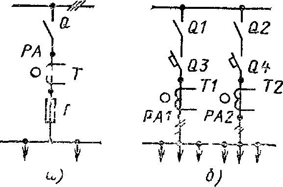
Installation of distribution boards The marking determines the location of the board in the room according to the design and the location of the installation site in relation to the parts of the building.
Fig. 7 2 Linear array PAR 11
a - scheme No. 04 b - scheme no. 47; Q - switch Р27 630 А Т - current transformer ТШ 20 0 б,
600 / 5А Г - fuses ПН2, 600 A Q1 Q2 - р) Silicones Р70 630 A Q3 Q4 - automatic circuit breakers А3736Ф 630 А Т1, Т2 - current transformers ГШ п0 0 5 600 / 5А PA, PA1 PA2 - ammeters
These works are carried out during the period of production of the basic construction works before the execution of clean floors and final finishing of the premises. At the same time, the main frame is fixed and fixed in the floor, on which the shield will be fixed in the future. The frame is usually made of channel steel. Simultaneously brackets and brackets for fixing equipment and insulators, as well as laying of the grounding lines and taps. After this, the construction organization makes the final decoration of the premises, including paintwork and laying of clean floors Door apertures should be sized to ensure the delivery of a switchboard assembled at the factory or in the MEZ in 6 currents or sections of several panels. Such shield units, assembled and pre-adjusted in workshops, are installed on the socle frame after completion construction work After aligning individual sections of the board in vertical and horizontal planes by plumb and level, the shield is finally fixed to the socket on bolts or by welding.
Attach sections to the foundation frame is not recommended until all sections are assembled, aligned and fastened together.
When transporting shields for long distances, the frame with tires and equipment is packed in boxes. The measuring instruments are delivered in drawers separately from the panels of the panel of the shield and parts thereof are sent for shipment from the factory or from the workshop. This marking, as well as working drawings of the shield are guided during assembly.
The measuring instruments are mounted on the switchboard and connected after all the other assembly work.
Control, protection, automation and measuring panels with EPP panels are designed for 110-35 / 6-10 kV substations with constant operational or alternating current of 220 V. The panels have a welded frame structure. Panel width 800, depth 550, height 2400 mm. Panels - open type with a vertical arrangement of clamps on the right and left sidewalls.
The installation of switchboards and control panels is similar to the installation of switchboards. Inspection of internal connections and assembling of individual panels in enlarged blocks is carried out in the Ministry of Economic Development during the preparation of the building part of the premises. Enlarged blocks of panels of panels and panels (without measuring instruments and protection relays) are transported to the installation site and installed on the embedded elements installed during the construction of the building part.
Distribution points (cabinets).

To distribute electricity in the shops of industrial enterprises, various kinds of distribution points are used.
Distribution points of the PRI series. The enterprises of the electrical industry produce items of the PR11 series in place of a series of distribution points of the PR9000 (Alma-Ata Low Voltage Equipment Plant and Bakelectroautomat Plant). They are designed to distribute electricity up to 660 V AC (50 and 60 Hz) and 220 V DC and to provide protection for the lines during overloads and short circuits. The points are equipped with circuit breakers of AE20 series in single-pole and three-pole versions with a rated current of 63 and 100 A. The circuit breakers of the series A3700, A3790 and AE20 for currents 100-630 A are provided at the terminals. The cabinets should be installed in a vertical position with a deviation of not more than ± 5 °. By the type of installation, the items have the following executions (Figure 7.3): recessed (for installation in a niche); hinged (for installation on walls, columns, structures) and outdoor (for installation on the floor). Degree of protection of shells: recessed-IP21, hinged and floor-IP21 and IP54 (see § 1.2). Dimensions of cabinets (L X H X B), depending on the scheme and design: recessed - from 750Х800Х Х200 to 750X1200X250 mm; hinged - from 650X400X200 to 750X1200X250 mm; Outdoor - from 650X800X200 to 750X1500X250 mm.
In cabinets, depending on the circuit, from 3 to 30 linear single-pole circuit breakers and from 1 to 12 - three-pole circuit breakers are installed. 
Fig. 7.3 Distribution point of the PR11 series of floor-standing version
The input switches of the cabinets of the hinged and floor versions are controlled by manual mechanical drive, the handle of which is installed on the front side of the cabinet. The handle has a lock locked in the disconnected position. The control of the outgoing line switches can only be carried out with the cabinet door open. The design of the cabinets allows the input of feed and outgoing lines with a cable with rubber and plastic insulation and wires in the pipes both from above and from the bottom of the cabinet through removable covers. Clamps of linear switches provide plug-in connection of copper and aluminum conductors of 6-25 mm2 (for AE2040) and 10-50 mm2 (for AE2050). The lead-in clamps of the points are also designed for plug-in connection of conductors.
Distribution points series PR22, ПР22Д, ПР24, ПР24Д, ПР24Н and ПР24Г are serially manufactured by Alma-Ata and Divnogorsk factories of low-voltage equipment. The rated currents of the A3700 - 400 and 630 A series circuit-breakers, the AE2000 - 63A series line switches and the A3700 series are 80, 160 and 250A. The number of circuit breakers on the outgoing lines is 4, 6, 8, 12 depending on the circuit.
The items are made of hinged and floor versions. The control conditions for the input and line breakers are the same as for the PR11D points. Input and output of the supply and outgoing lines is possible both by wires in pipes and by cable with rubber, plastic or paper insulation.
The connection of the conductors of the inlet and outgoing lines is plug-in. On the inner and outer sides of the cabinet, screws are provided for earthing the housing with a thread diameter of at least M8.
Dimensions of cabinets depending on the scheme: height - from 1100 to 1700 mm, width - 1000 and 1100 mm, depth - 300 and 350 mm.
Distribution cabinets of series ПР8501 and ПР8701 for rated currents from 160 to 630 A, equipped with circuit breakers of the BA50 series (see § 7.2). They are a new version of the switchgear, they are intended for power distribution and protection of electrical installations during overloads and short-circuit currents, for infrequent operational switching-on and off of electrical circuits and starting of asynchronous motors.
The cabinets are designed for nominal current - 160, 250, 400 and 630 A, according to the degree of enclosure protection - IP21 and IP54 (see § 1.2), according to the installation method - floor, hinged and recessed. Cabinets series PR8501 are designed for operation in networks up to 660 V AC, 50 and 60 Hz, the PR8701 series in networks up to 220 V DC. Cabinets can have automatic switches of the series VA51, VA55 and BA56 at the input. As linear switches in cabinets are installed single-pole circuit breakers BA51-29 and three-pole BA51-31 and BA51-35. A wide range of rated currents of releases of circuit breakers makes it possible to protect electric circuits and installations for various purposes.
These distribution cabinets of the series PR8501 and PR8701, equipped with automatic circuit breakers of the third generation of the BA50 series, will gradually replace the distribution points of the series PR11 and ПР20, complete with automatic switches of the second generation - AE2000 and A3700.
Distribution cabinets of the SHRS series are manufactured by the plants of NPO "Electromontazh" of the Mintmontazhspetsstroi for shop networks with a voltage of 380 V of a three-phase current of 50 Hz. The outgoing lines are provided with fuses PN2 and NPN2. Nominal current of cabinets with IP22 protection degree: 250 and 400 A. The number of outgoing lines depending on the circuit is from 5 to 8. Dimensions: at a nominal current of 250 A - height 1600, width - 500, depth - 380 mm; at 400 A - respectively 1600Х Х700Х580 mm. Execution - outdoor.
Power distribution cabinets with an automatic switch "Electron" type SHE (Figure 7.4) are designed for operation in direct current networks up to 440 V and AC up to 660 V, for protecting the circuits against overloads and short-circuits, as well as for infrequent switching on and off at nominal modes. 
Fig. 7.4. Power distribution cabinet with automatic switch "Electron" type SHE06V
Cabinets are manufactured with withdrawable circuit breakers E06B per 1000 A with a relay of overcurrent protection for 250, 400, 630, 800 and 1000 A and E16V at 1600 A with overcurrent relays for 630, 1000, 1250 and 1600 A. Cabinets with switches E06B can have a manual or electromechanical actuation drive, and with switches E16V - electromechanical drive.
Cabinets SHE06V have windows with removable plates. For the introduction of electrical wiring or cables on the installation in drill plates drill holes of the appropriate diameter. Cabinets SHE16V are designed only for
the busbar trunking of ShMA. All types of cabinets allow input and output of circuits from above, input and output from below or input from below and output from above (and vice versa). Cabinets ШЭ16В for input of conductors have a tire compartment.
Power relay cabinets ШС and ШР are designed for operation in direct current networks up to 500 V and three-phase current up to 660 V. They are equipped with control, protection and signaling equipment for electrical circuits of auxiliary needs of power plants, substations and other electrical installations.
Cabinets series ШС - power, ШР-relay. The cabinets have a metal casing made of sheet material. Four dimensions are available: ШС1, ШР1 - with dimensions 600X500X350 mm and ШС2, ШР2 - 1000X600X350 mm of hinged structure, ШСЗ, ШРЗ- 1400X800X600 mm and ШС4, ШР4 - 2000X900X600 mm of floor structure.
In the cabinets of the hinged structure, an oval hole is made in the lower part of the housing with a cover for the supply of wires or cables. Cable entry to the cabinets of the floor structure is made from a cable duct or pit.
Installation of distribution points and cabinets. The location of the point, the cabinet in the room and the method of its installation and fixing are determined in accordance with the working drawing. Fixing fasteners for the installation or installation of a point or cabinet must be installed during the period of basic construction works before the implementation of clean floors and finishing works. After the completion of the construction work, including finishing, the points and cabinets are installed and fixed in accordance with the working drawing, verifying the level and plumb, and the deviation from the vertical should not exceed ± 5 °. After that, external networks (wires, cables and grounding conductors) are connected.
Power boxes are the simplest switchgears up to 1 kV.
Power box YPP-15 UZ is designed for switching on, switching off and protecting three-phase 380 V circuits, including three-phase asynchronous motors with a squirrel-cage rotor. The box consists of a metal stamped case in which a three-pole PNV-30 starter is mounted at 12.5 A and three fuses E27 with a 16 A fuse-link
Assembly of the box. The input and output of wires of not more than 6 mm 2 are carried out through insulating sleeves with an internal diameter of 16 mm, installed in the holes in the upper and lower walls of the housing. The drawer is designed for connecting wires without end ferrules (under the ring). The case of the box is grounded by connecting the grounding conductor to the bolt on the right side wall of the case. To the same bolt, connect the zero wires of the supply and outgoing lines. The box is mounted on a plumb in the vertical position and secured with three bolts, for which in the back wall of the case there are three holes with a diameter of 6 mm. The drawer door should normally be closed. It is opened when it is necessary to replace the blown fusible insert.
The power box YARP-20UZ has the same purpose as the YAPP-15UZ. In the metal stamped case, a three-pole switch with a 20 A side handle and three E27 fuses with a 20 A fuse-link are installed. The door is locked with a switch so that it can only be switched on and off with the door closed.
Assembly of the box. The installation of the box and the connection of the wires are carried out in a manner similar to the installation of the YPP-15UZ.
Box of power YPPVU-1MUZ, YaB1-2UZ and YABPVU-4UZ. It is intended for protection of circuits and separate electric receivers, and also for infrequent switching on and switching off of three-phase electric circuits. The drawer consists of a metal stamped enclosure with a fuse-switch with PN-2 fuses built into it at 100, 200, 250, 315 and 400 A. The drawer door is locked with a breaker drive and can only be opened with the unit switched off. The unit can only be switched on with the door closed and locked.
Installation of boxes. The box is installed on a plumb line in an upright position. The fastening is provided by four bolts with a diameter of 6 mm for boxes of 100 A and a diameter of 8 mm for boxes of 200 and 315 A. Mounting holes are provided in the rear wall of the housing. To enter and connect the wires of the supply and outgoing circuits, remove the upper and lower covers of the housing and punch holes in them along the diameter of the pipes or glands that are introduced. Pipes of electrical wiring are fixed to the box body with the help of scratching grounding nuts. The tightening of the nuts is done gradually in order to avoid skewing the casing covers. When entering and removing wires from the bottom, the wires from the upper terminals are passed inside the housing under the block. In the output and input from above, respectively, the wires from the lower terminals are passed under the block to the top.
Before attaching the box, it is necessary to remove the protective shields that close the control terminal clamps and the rack of the unit. After connecting the wires, it is necessary to install protective shields that close the terminal clamps and the rack of the unit from possible contact with them, since they are energized when the unit is disconnected.
To replace the fused cartridge fuse raise the cartridge, release its upper tab from the groove of the upper holder and, lowering the cartridge down, take it out of the box. When installing the cartridge insert its foot into the lower holder, lift the cartridge upwards so that its upper foot wrenches the spring, and insert this tab into the groove of the upper holder.
Assemblies (boards) of control stations (magnetic stations) are used for automatic or remote semi-automatic control of the drive motors of various mechanisms. Control stations are manufactured in factories according to standard schemes, as well as special orders for individual schemes.
Due to the fact that there is a wide variety of technological processes that require the appropriate operating mode of the drive motor, a wide range of normalized stations and control units of the BU, PU, TSU, KTSU, etc. types is produced.
About these devices, known under the general name "low-voltage complete control devices for electric drives" (NKU), will be discussed below.
The stations and control units are supplied assembled on rack racks. Apparatuses with insulating plastic housings and slabs plants are mounted on metal rails, apparatus with enclosures that are under tension, on insulating racks. Plants of the electrical industry supply boards and assemblies of stations and control units in assemblies with sections up to 4 m in length. The boards and assemblies of the MN series are supplied in open version for installation in special rooms (control room rooms) or in enclosed cabinets for installation directly in the workshop.
Widely used open installation in the shops of control room panels in the form of closed cabinets with a set of standard control units, sliding type. Such blocks are a great convenience in operation, as they are interchangeable; in case of failure, the unit is moved out of the compartment of the block board and replaced with a backup one having a similar circuit.
In cases where an open installation in the control room panels of control stations can not be accepted, the installation of control stations, as well as the control posts of process mechanisms (for example, control of main drive mechanisms and rolling mill mechanisms) in so-called volumetric control stations ) and in wiring kits (EMC).
Installation of control stations.
Shields and assemblies of control stations of open type are delivered to the installation site after the readiness of the construction part and installed on the foundation bases in a manner similar to the above described installation of switchboards. Closed shields of control rooms of the cabinet type are installed in the shop on the prepared bases in a manner similar to the distribution points and cabinets. After installation, the shields are connected to the mains and to the motors. The installation in the shop of control stations and equipment of control posts mounted in EMC and SDS is reduced to their installation on prepared bases and to the connection of wires and cables of external networks.