Recommendations for choosing a gas boiler for different rooms
UPDATE OF THE AGV-80 WATER HEATER
In the process of operation of water heaters of the AGV type, certain shortcomings have been identified, which were eventually eliminated by upgrading individual units. Most of the changes occurred in the design of the gas burner assembly and the solenoid valve, which is now called the gas solenoid valve.
Fig. 1. Gas burner unit of water heater AGV-80:
1 - cover; 2 - a divider; 3 - a branch pipe; 4 - the bracket of the pilot burner; 5 - diffuser; 6 - union nut; 7 - connecting tube of the pilot burner; 8 - pilot burner; 9 - nozzle (nozzle) of the main burner; 10 - the knee; 11 - thermocouple
The upgrade of the gas burner assembly (Figure 1) consists in the fact that the main burner and the diffuser leading to it, previously made by means of cast iron, have been replaced with light stamping structures. The diffuser is made of bent pipe, its manufacture was simplified, the main burner became more compact, the installation and dismantling operations became more simple. In the modernized design of the gas burner unit, the mutual arrangement of the main and pilot burners and the thermocouple is also changed, this ensures a normal burner ignition process and a more reliable operation of the safety automatics of the water heater. The vertical axis of the pilot burner 8 from the vertical axis of the thermocouple 11 is at a distance of 30 mm.
The end of the thermocouple rises 5 mm above the edge of the pilot burner. It is necessary to follow in the process of working behind the location of the outlets of the main burner in the horizontal plane.
In order to ensure the reliability of the thermocouple, it is necessary to put a tightly fitting protective cover of heat-conducting material on it, which provides the required heating of the thermocouple junction and protects it.
Modernization of the design of the gas magnetic valve (Fig. 2) is as follows. The old design of the solenoid valve had a leather membrane that separated the gas and electric parts and was held in its nest by means of a clamping ring. A modern gas solenoid valve instead of these two elements has a molded rubber membrane 20. This membrane change caused simplification of the anchor rod 15, which now no longer has a cap at the lower end.
The biggest change is that the water heater is equipped with a traction sensor, which is attached with two screws under the hood of the water heater to its housing. In this connection, to the gas solenoid valve, instead of the tension nut with which the connecting tube of the pilot burner was previously connected, a tee 32 is installed which is intended to distribute the gas through two outlet nozzles: downwards to the pilot burner and upward to the draft sensor through the tube 29. Tee 32 are connected to the valve body on the thread, while a rigid throttle 23 with a millimetric cross-section is mounted between two two-millimeter rubber gaskets 24. The thrust sensor consists of a bimetallic element 16, at the free end of which there is a seal 34, and a bracket 18, to which a bimetallic element is fastened by means of two screws 27. In the bracket there is an opening for the fitting 36, which is clamped on top by a nut 35.
A fitting with a tapered end is provided which allows the through-hole bores 2,5 mm in diameter to be converted into the valve seat 33. The tube 38 with a tension nut 37 is connected to the union. This tube is connected by means of a union nut to the tube 29 leading to the gas solenoid valve.
Fig. 2. The gas solenoid valve with the sensor of draft of the water heater AGV-80:
a - gas cock; b - thrust sensor; 1 - cork; 2 - a spring of the bottom valve; 3 - sealing of the lower valve; 4, 7 - washers; 5 - lateral drilling on the pilot and thrust sensor; 6 - the valve stem; 8 - housing; 9 - the base of the magnetic box with the connecting bracket; 10 - winding of the core; 11 - the core; 12 - Anchor; 13 - a spring; 14 - button; 15 - anchor rod; 16 - bimetallic element; 17 - nut; 18 - bracket; 19 - the cover of the magnetic box; 20 - rubber membrane; 21 - a plate of the top valve; 22 - sealing of the upper valve; 23 - throttle; 24 - rubber gaskets; 25 - the plate of the bottom valve; 26, 28, 30 - gaskets; 27 - the screw; 29 - the tube of the gauge of draft; 31 - union nut; 32 - T-piece; 33 - the valve of the gauge of draft; 34 - compaction; 35 - the union nut; 36 - fitting with 2.5 mm nozzle; 37 - the tension nut; 38 - pipe fitting.
All the work of the traction sensor is as follows. If there is no draft in the chimney, when heating, the combustion products enter the room through the gap between the edge of the hood and the body of the water heater and the bimetallic element 16 unbends its arc, since the coefficient of linear expansion of the material of its inner surface is greater than the coefficient of linear expansion of the outer one. Therefore, the valve 33 with the seal 34 will move away from the conical end of the nozzle 36, thereby releasing the gas outlet from the connection tube 29 to the room with the water heater placed therein. Since the orifice opening 36 is 2.5 times the diameter of the throttle 23, the pressure in the tube 29, the tee 32 and the tube guiding the gas to the pilot burner will immediately drop. This is due to the fact that the gas, which is directed inside these elements through the throttle 23, does not retain pressure in them if there is a drop through the opening (2.5 mm) of the thrust sensor connection. Reducing the pressure at the inlet to the pilot burner can extinguish the flame on the last burner, which leads to the cooling of the end of the thermocouple and the activation of the gas magnetic valve. For this reason, the solenoid valve stops the gas supply to both burners of the water heater.
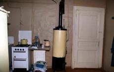
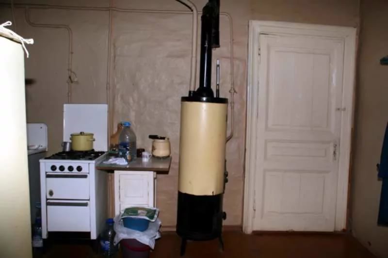
AGV - 80 gas heating boiler. Technical characteristics of agv-80:
The main components of the AGV-80 heating boiler.
- Galvanized tank (80 liters) thermal insulation, min wool. In the center of the tank is a flame tube with a heat flow extension.
- The main burner, in front of it, the valve regulates the supply of gas.
- Automatic security.
- The flame is an electro-magnetic valve, thermocouple, igniter.
- By traction tee, connected pipe, traction sensor.
- Temperature is a temperature regulator.
Electro-magnetic valve of the boiler. The electro-magnetic valve of the boiler consists of 2 parts gas and electromagnet. Between them is a membrane. The thermocouple consists of two metals, chromel and copes, that are spilled together. The flame heats the boiler thermostat forming an electric current which magnetizes the core. Pressing the starting button, the anchor is pushed against the core by the pusher, while the paired valves are shifted to the inside of the gas part, opening the gas to the igniter of the boiler and compressing the return spring. After the warm-up of the 60-second thermocouple, the boiler button should be gradually released, and under the action of the return spring, the paired valves shift backwards - 2.3 mm. The gas opens, both on the igniter and on the main burner of the boiler. The valve can not return completely to its original position. They are held by an anchor magnetized to the core. If the fuse is extinguished, the thermocouple of the heating boiler cools down and the magnet releases the anchor. The return spring pushes the valve back to its original position, the gas does not flow on the burner.
Malfunctions of a gas heating boiler AGV-80
- Contamination of the core and anchor surfaces (clean, degrease)
- Thermocouple burned (Replace)
- There is no electrical contact.
Automation for traction (With gas removal from the igniter)
Gas from the electro-magnetic valve of the heating boiler, through the tee, goes to the igniter, and also through the connecting tube to the thrust sensor installed under the hood of the device. The traction sensor is a Bimetallic plate with a plug, which, with normal draft, closes the gas from the connecting tube. When the traction is closed, the combustion products come out from under the hood and heat the bimetallic plate. It unbends, the cap opens the gas from the connecting tube, gas is supplied to the igniter. Response time from 10 to 60 sec.
Thermostat gas boiler. Accuracy of operation 5grC, details of the temperature regulator.
- Housing.
- The system of shift levers.
- Valve with spring.
- The brass tube with the invective bar is screwed into it.
- Lever for thermostat.
When the water in the tank is heated, the brass tube is lengthened, and the intar core is not. The rod moves behind the tube and stops pressing on the system of closed levers that shut off the valve by a click of a spring, block the gas passage to the burner, when the water cools, the brass tube shortens the rod and presses the levers, they shut off and turn off the valve. When the adjustment lever is rotated, counter-clockwise, the operating temperature increases.
 Malfunction of boiler thermostat.
- The thermostat does not work does not work:
- Stretched or burst system of levers.
- Deformed large or small levers.
- The bearing edges of the levers were worn out
- The thermostat operates but does not stop the gas supply:
- The valve spring is loose.
- The dirt got under the valve.
- The valve stem is set by the guide bush.
AGW, or automatic gas water heater is an element of the heating system, through which it acquires ease of operation along with a sufficiently long service life. However, the presence of these characteristics is possible only in case of correct installation and competent maintenance of the gas boiler.
Epilogue
In conclusion, it is worth recalling that repair of AGV, along with maintenance of gas boilers - is quite a complicated operation that must be carried out by specialists. Only by observing this condition can you exclude the risk of damage to housing and injury to its occupants.
To date, the production of gas boilers AOGV engaged Zhukovsky engineering plant, which for many years produced military equipment and supplied it to the front, and after a time produced components for space equipment. Read and about the typical breakdown.
AOGV gas boilers are designed for a low level of fuel and water pressure, and are also "ready" for a low-quality heat carrier.
In addition, the low temperature on the street, nor the harsh climate of the regions can not interfere with the work of the heater.
How to choose AOGV heating gas boilers?
Heating equipment produced at ZHMZ is the best water heating equipment of domestic production. All devices are designed for a long time of use.
When choosing a boiler AOGV should be guided by the size of the heated room, its area. For example, the most powerful device can provide a warm living space of 600 square meters. AOEV equipment is even used for heating large estates.
Types of AOGV heating gas boilers
The most important advantage of AOGV heating equipment is consumer characteristics. Instruments feature a high degree of endurance and reliability, which automatically makes them comfortable for use in Russia.
AOEV are floor gas boilers, which are represented in Russia in three modifications:
- "Economy" is equipment equipped with automatic control unit of domestic production;
- "Universal" - is multifunctional, adaptive, assembles on the basis of foreign components;
- "Comfort" - assembled using a foreign automatic control system;
The most common and purchased models of AOGV heat equipment:
The efficiency of the AOGW heating equipment is 89%. For domestic equipment intended for space heating, this indicator is high.
Installation and connection of AOGV gas boiler
Gas heating boilers AOGV are comfortable for installation in a multi-apartment building. The heating unit can be connected on any surface if the following points are taken into account:
- 2.5 meters - the level of the height of the unit;
- There is ventilation in the room where the boiler is installed;
- Extraction is necessary;
- V premises must be calculated for V boiler;
- It is necessary to have an emergency exit, which will be necessary in case of force majeure;
- Cover the installation site with fireproof flooring.
Operating Instructions for AOGV Gas Boiler
To each heating device manufactured at ZHMZ is attached:
- Warranty card;
- User's manual.
In the manual, you can easily find items about installing, adjusting and connecting a gas floor boiler.
Also in the instruction manual, all possible failures and ways of their elimination are registered. For example, the most common breakdown is the damping of a gas boiler. In this case, check the integrity of the injectors and the gas supply. Interfere with the internal design of the boiler does not follow, because a violation of the integrity of the heater will lead to a loss of warranty.
Spare parts for AOGV gas boiler
In the event of a breakdown, the failed parts of the AOGV gas boiler can be replaced. For example, you can change the thermostat for the AOGV gas boiler without special special skills or, with the help of specialists, replace the thermocouple and automatic (automatic control system).