How to connect the triple switch correctly. How to connect a three-key switch
In an effort to improve the convenience of managing electrical appliances, manufacturers are creating new types of functional devices. One such is triple switch. What kind of design has a three-key switch and what nuances to take into account when connecting the device, we will consider in more detail.
Switches of this type with standard dimensions of devices are equipped with three keys located close to each other. Their main purpose is to provide the possibility to control simultaneously three groups of connected lighting devices from one common access point.
Most often, these devices are installed in rooms with a complex configuration: combined bathrooms, long corridors, combined with the kitchens of the living rooms.
The three-key switch is conveniently used for controlling both main and auxiliary lighting, for example, for implementing a diode illumination scheme "ceiling / wall / floor"
Three-key devices are convenient to use for controlling multi-chandelier chandeliers. To obtain three versions of saturated light, they can be included in three stages, in which first one lamp lights first, then the next two.
Among the indisputable advantages of three-circuit devices is:
- Presentable appearance.
- Saving of the occupied area.
- Ease of installation.
Simplify the installation procedure three-key switch is achieved due to reduced labor costs in creating a common technological niche for placing the core of the device and laying an electric cable to it.

With properly selected electrical parameters and proper compliance with the mode of operation of the three-key device, even a budget switch model can safely work for many decades
The design of the three-key switch is quite simple. It includes two components:
- The internal part, which is a mobile mechanism, where the process of closing / opening the network under the action of compression / extension of the spring is carried out.
- The outer part, which is a box with a switch-key, to which the contacts are permanently attached.
Since the load on such devices in comparison with simple types of models is somewhat higher, the internal elements and the external housing are made only of high-quality materials.
Main types of closing devices
Switches, including triple ones, depending on the method of control are keyboard and touch performance. The first are set in motion by pressing a key, the second - by touching the panel in a certain place.

Most models of sensor switches are equipped with a dimmer - a device for a smooth six- or seven-stage adjustment until the light turns off
When choosing a dimmer it is important to focus on the total load of the switch. Specialists recommend purchasing devices with a power reserve. For example: for a three-legged chandelier with lamps with a power of 100 watts, select a dimmer with a marking of 300 W.
Depending on the type of installation triple switches are of three types:
- for external installation;
- interior, suggesting penetration into the cavity of the wall;
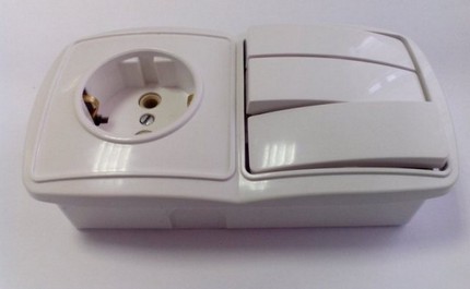
- combined models having a common housing with a socket.
Combined models equipped with a socket have a narrower scope. This is due to the fact that their installation is impossible without reworking the wiring.

When installing a combined-design unit to the same point, two separate wires for the socket must be supplied and at the same time, the phase conductors for lighting
Installation triple switch, combined with a socket in the common housing, is justified in those situations where it is supposed to equip the open wiring. The rules of electrical safety strictly regulate the height of placement of switches and sockets - 150 cm from the floor. For this reason, such models are installed in places where the sockets are operated quite often, provided that the switches at this height are convenient to use.
The most common combined models were obtained in the arrangement of bathrooms with accommodation near the mirrors and bedrooms in the area of the bedside tables.
Separate subspecies are allocated triple wireless switches, which can be installed anywhere and placed on any surface.
The wireless model is a switch of a different type, which is more similar to the construction device with a remote control
Wireless devices are equipped with two modules:
- Receiver is a relay type device built into the light source. When the signal is received, it closes the lighting circuit.
- The signal transmitter is a switch itself, equipped with an energy generator. When the button is pressed, it recycles the energy pulse into the radio signal.
Such high-tech devices are among the most expensive. Instead of the usual wiring, they use infrared or radio waves.
There are also light switches on sale. They are convenient in that they create a light signal in the dark, which serves as a good reference point for a quick finding of the device.

The backlighting on the switches additionally acts as a pointer, which signals an inoperative lighting condition, since it turns on when the voltage is not applied to the instrument
When choosing such models, it is worth paying attention to the type of lighting source. Switches with illumination do not cause trouble only when connected in a chain with ordinary incandescent lamps or their halogen counterparts. If fluorescent lamps or LED strips are used in a circuit with such a device, even with the switch off, they will continue to emit a light pulsating glow.
Eligibility Criteria
By purchasing a triple switch, carefully inspect it, examine the physical quantities, check the connection diagram. The main points that should be considered when choosing a product:
- The body of the product - it should be devoid of any kind of defects: burrs, dents and chips.
- Keys must be operated easily and without jamming.
- Sound effects - when you turn on each key, you should hear a characteristic click.
- The core - should also be devoid of burrs, and its terminals work properly.
When planning to install a switch in a room with high humidity, it is necessary to choose a device with protection.

The working elements of the waterproof switch have an additional rubber or plastic sheath that protects the mechanism from direct contact with water
To simplify the installation procedure and to ensure the durability of the device, preference should be given to models whose cores are equipped with screw or clamping terminals.
Device connection technology
The connection of three-key switches practically does not differ from the technology of mounting one- and two-key analogs.
The idea is that one of the supply cables is connected to the input of the switch, and the cables of the lighting devices to the input terminals of the connection blocks. The difference is only in the total number of contacts of the switching groups involved in the case of the device.
Preparatory work
The first thing to do before connecting or disassembling a three-key switch is to switch off the switch for the time and make sure that the network is de-energized. Before starting work, you need to understand the wiring to which the device box is supposed to be mounted.

According to this wiring diagram, when installing the unit for the installation of the combined model from the junction box, separate the zero conductor, which will ensure the functioning of the outlet
The circuit breaker can not be connected without the following tools:
- voltage indicator;
- tool for stripping;
- cross and flat screwdriver;
- a perforator equipped with a crown;
- building level;
- insulating tape.
When the breaker is internally installed, the core of the device requires a pad and a small portion of gypsum or alabaster. For the assembly of wires and the connection of contacts inside the junction box - self-clamp terminals.
Assembling the wires in the junction box
Two wires are fed from the shield to the junction box. Identify their affiliation easiest by the color of the braid and labeling:
- "Zero" - painted in blue;
- "Phase" - has a brown braid.
For reliability of conclusions at definition of an accessory of wires it is better to take advantage of the tester.
From the lamps in the junction box, there are six wires. The master's task is to connect three of them among themselves, and then connect them to the working zero coming from the flap. The remaining three wires will only be sent to the switch and docked with its outputs.

The wires lead to the junction box are connected together, using self-clamping terminals or using the usual twisting method
The main points that should be considered when assembling wires in the cavity of the junction box:
- The zero of the supply wire is connected to all the "zeros" of the powered fixtures.
- The phase of the supply wire is connected to the common contact of the switch.
- The remaining three wires coming from the switch are connected to the corresponding three phase wires coming from each lighting device.
By connecting to the release one common phase for all light sources, a circuit is created, at which moment one of the switch contacts lights up one or another lamp.
Mounting of the receptacle into the niche
The dashboard is only used when installing the internal installation switches, the core of which is halfway into the wall. The main requirement when installing the juniper is that its edges are flush with the wall and do not protrude beyond it. Otherwise, after the core is installed, the switch body will protrude from the wall.

To penetrate the core of the device into a niche in the cavity of the working surface with a perforator equipped with a crown, a hole is made to a depth sufficient to accommodate the "glass"
Presented in the sale of jelly can vary in color, shape and the presence of lateral protrusions. If, on the basis of taking the method of installation, the "glasses" are divided into two types:
- For concrete - solid structures that are fixed in the wall by plastering or plaster.
- For gypsum cardboard - the structures are equipped with special paws, with which they are flung in the wall.
Regardless of the design, any padding is equipped with pressed holes through which an electrical wire is inserted into the cavity of the structure.
"Glass" with the wire wound into it is buried in a previously made niche, leveled with a level along the horizontal and vertical plane and fixed in the wall.
Wiring diagram of a 3-button switch
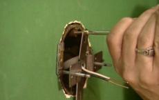
To access the triple-trigger mechanism, the device takes out the keys and removes the decorative frame. This work can be done with a flat screwdriver. To extract the key, you just need to press it, turning it to the "off" position, and protruding from the opposite side of the edge gently, without applying excessive force, to tip the screwdriver.

In fact, from the back side of the triple switch it is easy to see where the phase is being brought, and where the wires coming from the lamps are connected - they are divided into separate pads
Four wires will be supplied to the installation site of the switch. They can be combined into a four-core cable or a combination in which:
- phase solid conductor comes from a junction box;
- three-core, which through the switch box provides a phase for the connected lighting fixtures.
The neutral wire will pass directly from the junction box to the lamps, bypassing the switch.
The incoming phase is connected to the input terminal marked with an arrow, and three outgoing terminals to the output wires of the luminaires. Which output to which terminal, does not play a special role. If you want a specific terminal to be responsible for exactly this luminaire, recompression of the wires will not cause any special difficulties.
The wires in the mechanism are fixed by means of clamping screws. Before inserting bare ends, it is important to make sure that the rods of the screws are not completely twisted into the grooves. By inserting the ends of wires from the braid into the mechanism, tighten the screws tightly. When checking the wires for extraction, there should be no play.

In the mechanism, the common terminal for the phase conductor is first separated and only then are the terminals for supplying voltage from the individual lighting sections
The main rule for connecting the circuit of a three-key switch is that a non-zero, but a phase-to-phase power wire is connected to the input of the device. Zero network wires are connected exclusively to the "zeros" of lighting devices. This rule is strictly regulated by the current regulation - the EEI.
Some craftsmen neglect this rule, directing the phase wire to the lamp, and "zero" by feeding it through the breaker. With this version of the assembly, the network will still work. But such a decision is fraught with danger in the operation of the electrical system, since even with the circuit breaker disconnected, the wiring will still remain energized.
It is dangerous that even with the usual replacement of bulbs a person will always be at risk of electric shock. And if there is an insulation breakdown at all, and there is no grounding of the connected lighting device, voltage will appear on the device body. As a result, the slightest contact with the surface of the device will cause an electric shock.
Features of installation of combined models
The circuit diagram of the circuit-breaker connected in a common housing with a socket differs somewhat from that described above. And the main difference - the presence of an additional zero wire, laid from the junction box directly to the outlet. In this case, the output from the switch will have two double wires.

When connecting stranded wires to prevent them from breaking off under the pressure of the screw clamp, the bare sections of the cores are equipped with NSHVs with tips
To make a safe connection of the switch with a socket, it is better to use a wire with a cross section of 2.5 mm2. And already directly to the lighting devices from the switch lay the cable in 1.5 squares.
At the final stage of installation it remains only to check the correctness of the wire switching and to install a decorative frame. To check the correct connection, you need to turn on the power switch and apply power. When the first button of the device is turned on, one lamp should light, while the second one - the next chandelier horn or the connected appliance.
The frame is fixed using a clamping insert. It is necessary to slightly press on it and with a small effort to snap it on the sides.
Connection sequence of triple breaker:
The variant of assembling the three-key switch with the socket:
When assembling the device in accordance with the wiring diagram and adhering to the safety during installation, you can be sure that the switch will function smoothly for many years.
A two-button switch is used to turn on the light in two different rooms, for example in a bathroom and a toilet. In private houses and cottages, such a switch can be installed in the entrance door, so that light from one key is switched on in the corridor, and on the other -. Also, two-key switches are used to connect chandeliers when, when the first key is turned on, one group of lamps lights up, when the second key is turned on, another group of lamps, and when both keys are turned on, all lamps simultaneously.
Applications two-key switch there may be many, but the scheme of its connection in all these cases is the same.
The two-key switch has two keys that can be in one of the positions: off or on. The direction of inclusion is the same.
To connect the wires, this has three connecting clamps: one clamp for the incoming phase wire and two clamps for the outgoing wires. Typically, the input terminal is on the opposite side of the outgoing wire clips. The switch clamps of some manufacturers can be marked. Before starting work, you need to turn off the electricity with the help of an automatic device located in the electrical panel on the landing. The absence of voltage is checked by the indicator screwdriver.
Wiring of two types: self-clamping terminals and screw clamps. Minus screw terminals - in the gradual easing of the screw connection and the need for periodic tightening of the screw. Therefore, in circuit breakers, the mechanisms with self-clamping terminals are more often used.
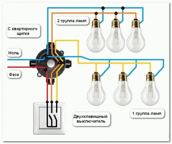
Connection of a two-button switch can be represented as the following scheme:

With the switchboard in the junction box, two wires come in: the phase (red) and zero (blue). The phase (red color) from the junction box is connected to the wire (red) going to the common terminal of the double-switch switch. From the switch go two (marked yellow and orange).
From the ends of the wires it is necessary to remove the insulation by about 3-4 cm, the wires are to be spread in different directions to avoid short circuits.
One wire (yellow) is connected in the junction box with the phase conductor of the first luminaire or with the twist of all the phase wires of the first group of bulbs.
Another wire (orange) is similarly connected in a junction box with a phase conductor of the second or with twisting of all the phase wires of the second group of bulbs.
"Zero" wire (blue), which goes to the junction box from the electrical panel, is connected to the "zero" wires of all lamps. That is, the "zero" wire goes directly to the lamps through the box. Thus, the switch commutes only the phases.
When connecting a two-button switch in the box, you get four connections:
- The phase wire of the box with the common terminal of the switch;
- The phase output from the switch to the first group of lamps;
- Output of the phase from the switch to the second group of lamps;
- Zero wire that goes directly to the lamp.
When calculating the number of wires inserted into the junction box at a given, they are obtained eight:
- two with the apartment switchboard: phase and zero;
- three on the switch: the general phase and two switched phases of different groups;
- three for lamps or lamps: a common zero and two switching phases with two switch buttons.
 The circuit will look like this if the bulbs (lamps) are near (in one chandelier). If one luminaire is in the corridor (bathroom) and the second one in the kitchen (in the toilet), then in this case there will be more outgoing wires, as each cable will go from its own cable (wire).
If it is made with a grounding system, three wires come into the junction box: red (red), zero (blue) and ground (yellow-green).
In this case, the circuit for connecting the two-switch switch is made one-on-one with the previous circuit, with the addition that the protective conductor in the junction box is connected to the common twist of the protective wires from the luminaires or chandelier.
The fact that the breaker must break the phase, not the zero, is done for the purpose of safety. Then, when replacing the bulb in or the lamp, it will be sufficient to disconnect the switch and there will be no voltage in the cartridge. And if the switch is switched to zero, then when the bulb is replaced in the cartridge, the phase potential remains, i. voltage.
If there are more than three lamps or a more variable light change is required, a three-key switch is used. It is connected in exactly the same way as the two-key, that is, the phase wires from the three groups of luminaires are connected to the corresponding phases of the switch.
When it is necessary to turn on the lighting from the corridor to the bathroom and toilet, and also manage the multi-level lighting and in a number of other cases. use the triple-switch connection scheme. The complexity of connecting a three-key switch is not higher than connecting one or two key lighting scheme.
Wiring diagram for three-key switch
By design, the 3-key switch also does not differ much from the two-key device. The difference is only in one additional contact and the third key. A triple switch is installed in the jar. In the wall, a drill hole is made with a crown to fit the size of the podzetetnik.
Before attaching the receptacle, wires are drawn through its opening. The cover is coated with a creamy solution of building gypsum and placed in the hole. Surplus of the extruded solution of gypsum is removed, and the wires in the podrozetnika are tightened.
When installing the connection scheme of the three-key switch, a four-core copper cable, 1.5 mm² cross-section, must be connected to the sub-socket. One conductor is connected to the phase in the distribution box, and the other end of this conductor is connected to the common contact of the triple switch.

Wiring diagram of the three-key switch is displayed on the rear panel
The three remaining wires are connected to the three switch contacts that are on the opposite side of the common contact. 6 phase conductors, three wires from light sources and three wires of a three-pole switch must come into the junction box.
Three zero wires of the lighting lamps are connected together and connected to the common neutral wire in the junction box. The three remaining phase wires are connected to the three wires coming from the contacts of the triple switch. All wiring connections are conveniently done through the Wago connection terminals.

Wiring diagram for three-key switch
If the colors of the insulation of the wires are different, the connection is made from the side of the light bulbs and the switch contacts according to the order of switching on the lighting in the premises according to the earlier marked colors. When the wires have only one color - white, the connection is made in random order.
The necessary order for the inclusion of individual keys is determined after the voltage is applied. If the connection scheme of the three-key switch does not match the lighting of this room, then pencil marks are made - which room lighting is switched on by each key. After all the keys have been numbered, disconnect the mains voltage and change the order of connecting the contacts on the switch at your discretion.
Remember, for safety reasons, all electrical work is done when the mains voltage is off. Before connecting the three-key switch, do not forget that the breaker should break the phase, not the zero. It is necessary that the wiring is not energized when the lighting is off, and for electrical safety when replacing the light bulbs.