Do-it-yourself electric soldering iron “Moment” using improvised materials. DIY soldering iron from an electronic transformer Homemade small-sized soldering iron moment on a pulse transformer
Making it is not difficult for a person versed in electronics. A soldering iron is the main tool of any craftsman who repairs and creates electronic equipment. A standard soldering iron is equipped with a heating element, which consists of wire made of nichrome. The heat generated during the heating process is transferred to the copper tip. A soldering iron can be easily made at home. One of the disadvantages of this design is the time required to heat the soldering iron tip. A home-made pulse soldering iron does not have this drawback. A homemade tool with a pulsed operating principle heats up to the desired temperature very quickly, in fact within five seconds or even faster.
The pulse soldering iron is used for assembling elements and assemblies of electrical products.
Most often, the tip of a tool that has a pulse operating principle is made of copper wire with a diameter of 2 mm. A pulse soldering iron is very convenient when soldering small parts with frequent breaks during work and in cases where urgent work is being done.
Pulse soldering iron device
A pulse soldering iron is a device designed for carrying out installation work when assembling circuits of electronic devices. The heating element of such a device is a sting made of copper wire. The working element is heated by passing a low voltage electric current through it. The pulse type tool uses a small amount of electrical energy. The high efficiency of such a soldering iron is due to the fact that electric current is passed through the working tip only during the soldering process. The device consists of a converter of mains electrical voltage into high-frequency voltage. The output converter produces electric current with a frequency of 18-40 kHz. In addition, the device includes a high-frequency step-down transformer and a microprocessor control circuit. The secondary winding in a step-down transformer has current collectors at its ends designed to secure the tip to them.
![]()
Pulse soldering iron transformer circuit.
The tip is attached to the current collectors using bolts. Modern pulse devices for soldering have in their design power level indicators and effective illumination of the work area. The body of a modern instrument is made of heat-resistant plastic.
The advantages of such devices are low power consumption, low weight of the instrument and compactness, which is ensured by the use of modern high-frequency converters in the design. Some devices have, in addition to an indicator, a power regulator, which allows you to work with both small products and large-sized electronic circuit parts. A pulse soldering iron should be used carefully when soldering electronic components that are very sensitive to high-frequency voltage that appears at the tip of the device.
Return to contents
Making a soldering iron with a pulse operating principle
The design of the simplest instrument of the pulse operating principle includes the following structural elements:
- transformer of electronic operating principle;
- LED indicators;
- copper wire for making a tool tip;
- on/off button;
- plastic case;
- dielectric stand.

Electrical circuit of a pulse soldering iron.
The design of a pulse soldering iron is much more complex than that of a conventional tool that has a heating element in its design. In order to make a pulse soldering iron with your own hands, you will need to prepare an electronic transformer.
To make it, you can use a switching power supply used to run fluorescent lamps with a power of 40 watts. The transformer from such a power supply requires some modification. Its essence lies in the fact that it requires removal of the secondary winding and installation of additional winding in the form of one or two turns of copper wire with a diameter of 1 mm. The finished transformer with a modified winding is placed in a pre-prepared housing. The most convenient form of the case will be in the form of a pistol, in which a button is mounted in place of the trigger to turn on the device.
In place of the imaginary gun barrel, a stand made of dielectric is mounted, onto which a loop of copper wire is attached - the sting. It is connected to the secondary winding of the device’s transformer; when the circuit is closed using a trigger button, the tip heats up. To visualize the operation of the tool, you can solder an LED into the circuit. During operation, you should not hold the power button in the “on” position for a long time, as this can lead to overheating and rapid failure of the device.
Return to contents
Making a pulse microcircuit soldering iron
The design of the microcircuit tool includes the following structural elements:
- a resistor that acts as a power supply;
- means of electronic protection against failure;
- device body;
- LEDs.
The difference between a microcircuit soldering iron and a conventional pulse-based tool is the presence in its design of a circuit that prevents overheating. Such devices use special devices to protect microcircuits from overheating and breakdowns. Their device uses a resistor as a power supply. This component of the device must have an adjustable output voltage that varies from 0 to 15 volts. The element that ensures heating of the tip in the design of such a soldering iron is an MLT resistor with a resistance rating of 8 Ohms and a power of 0.5 W.
To make such a resistor, you need to remove one leg of the element and make a hole in the place where it is attached. For this purpose, you can use a drill using a drill with a diameter of 11 mm. In order to ensure safety, you need to use a piece of mica to protect the end from contact with the internal cavity of the bowl of the resistor being converted when the tip of the tool is inserted. To visualize the operation of the device, you can install an LED indicator in the voltage supply circuit, which lights up when you press the power button.
A homemade pulse soldering iron allows you to easily carry out the process of soldering any components of an electronic circuit.
Do-it-yourself pulse soldering iron - not easy, but very simple!
Radio amateurs are making more and more equipment for their work independently. The pulse soldering iron was no exception. You can make it yourself.
Experienced radio amateurs well remember the domestic instantaneous heating pulse soldering iron “Moment” with a light bulb near the heating element.

This technology has not been forgotten today. In radio stores you can buy a soldering gun for a reasonable price. What if it's free? Easily! You can assemble such a device from elementary parts that are available in the workshop of any homemade product.

First, let's look at the design of a soldering iron that operates on the pulse principle.
The working tip is a piece of copper wire with a diameter of 1-3 mm (depending on the parts that need to be soldered). The working tip is heated by passing a large current through it at a minimum operating voltage.
The principle of short circuit, or spot welding. Another design element is a 50 Hz mains voltage converter into a high-frequency one, with a frequency of tens of kilohertz. The secondary winding is connected to the current collectors of the working tip.
The device is quite economical. Mainly due to short term use. The main difference from a regular soldering iron is that it does not need to be kept on all the time to maintain operating temperature. The tip heats up within a few seconds. Therefore, most of the time the device does not consume electricity.
How to make your own “Moment” soldering iron from a house-saving lamp
It is necessary to find used components from old household electrical appliances:
- Converter (ballast) from a fluorescent lamp. Enough power 40 W;
- Working transformer;
- Copper wire 2-3 mm in diameter;
The case, or rather the manufacturing technology, is not important.
Device diagram:

In fact, everything that we see on the circuit diagram to the left of transformer Tr1 is part of the ballast from the energy-saving lamp. The device is complete; there is no need to modify it or change components.
The characteristics of the converter are quite suitable for a medium-power pulsed soldering iron. The safety of the design is enhanced by a standard fuse and overheating control using a thermistor.
The circuit turns out to be compact and can be placed in any housing.

The working transformer is made independently. A ferrite ring from a broken electronic transformer is suitable for this. The size must be sufficient to accommodate the windings. We wind the primary from 0.5 mm wire. The number of turns is 100-120.

The secondary (power) winding is made of wire with a cross-section of 3-3.5 squares. We make one turn. A soldering iron tip made of copper or nichrome wire 1.5 - 2 mm is attached directly to it.
IMPORTANT! The thickness of the secondary winding must be greater than the thickness of the tip.
A pulsed soldering iron made from an energy-saving lamp is ready. All that remains is to come up with a convenient housing for it, install a switch, and you can quickly repair electrical appliances.
Pulse soldering iron from a Chinese transformer
It is necessary to find a working 12 volt switching power supply, or one with a burnt-out secondary winding. Any Chinese device with more or less adequate components will do.

We remove the circuit from the case and check the serviceability of the parts and installation. We leave the converter untouched; to remake it, you only need to change the transformer configuration.

Carefully remove the secondary winding of the transformer. To make a new one, we need copper wire with a cross section of 1.5 - 3 square mm. If the cross-section is small, fold the wire in half. There is nothing wrong with such a solution, the overall cross-section is important to us, it must be at least 3 squares.
The winding consists of one incomplete turn. Carefully thread the resulting winding into the transformer body, having previously bent it like a hairpin.

We solder the transformer back to the control board, and fix the new secondary winding with any dielectric glue, for example, cold welding.

The most important thing is safety precautions when working with a soldering iron, so we return the circuit back to the case.

A wooden handle from a regular soldering iron is perfect as a handle. Options are possible, given the overall compactness of the device. We install a non-fixed switch in the handle.
IMPORTANT! The operation of a pulse soldering iron is based on a short circuit of the secondary winding; prolonged heating can lead to a fire and destruction of the transformer.
Therefore, a latched starter is not acceptable.
We assemble the device completely, all that remains is to install the clamps for the tip.

Inserts from the junction box for electrical wiring can be used as clamps.

The soldering iron is compact and convenient to use for small soldering jobs. The replaceable tip allows you to change its configuration.

Conclusion
The two options considered are only a small fraction of the various schemes for manufacturing such devices.
The main thing is to understand the principle of operation:
- Voltage to high-frequency converter (setting part);
- Step-down transformer designed for high frequency;
- Power winding forming a closed ring with a loop-shaped working tip.
And in conclusion, a video in which everything is shown in detail and tells how you can also make a pulse soldering iron
The device is reliable, economical, and, as it turned out, practically free.
A simple pulse soldering iron based on an electronic transformer
This idea was born after a good friend made a similar soldering iron, which used an ET (electronic transformer) to power 12-volt halogen lamps. In fact, I didn’t come up with anything new, I just assembled a similar soldering iron using a more compact and low-power 50-watt electronic transformer. Unlike high-power ETs, the transformer is made on an W-shaped core; winding the required winding is very inconvenient, so first you need to desolder and disassemble the transformer.


The circuit of such ETs is standard - a half-bridge inverter, unlike the circuits of the manufacturer Taschibra, this unit is quite stable, there is no separate OS transformer, and the basic windings of the switches are wound on the main transformer. See the diagram below.


The soldering iron turned out to be quite light, the tip heats up in just 5-6 seconds. It can be used for installation work, but for larger-scale tasks (tinning boards, etc.) such a soldering iron is not the best option.
List of radioelements
DIY pulse soldering iron
DIY pulse soldering iron

Post pulse soldering iron circuit It came to mind after I came across it on one of the forums. The advantage of pulse homemade soldering iron is the rapid heating of the tip, and also the convenience of soldering small parts.
This is a soldering iron with a low-power, compact 50W electronic transformer inside. Unlike high-power ETs, the transformer is made on an W-shaped core; winding the required winding is very inconvenient, so first you need to desolder and disassemble the transformer.

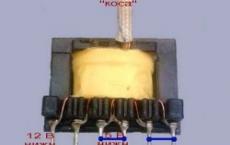
A 12 Volt winding consists of 8-10 turns of 0.8-1mm wire, we need to unwind this winding and wind a new one.


The power winding consists of only one turn; the winding is done with a busbar with a cross section of 5-6 mm. In my case, a screen from a television cable was used as a bus.

After winding, the winding needs to be given some durability. To do this, pieces of cardboard are inserted into the sides of the core.
Previously, I had a German soldering iron in the form of a pistol. The basis of operation of such a soldering iron is the same as that of a pulsed soldering iron, only it uses a network transformer. Working with this soldering iron is extremely inconvenient due to its heavy weight, and when turned on for a long time, the transformer overheats very much (once the mains winding even burned out, I had to wind it myself).


In our scheme there are no such shortcomings; even without heat sinks, the heat generation on the keys is insignificant.
The ends of the bus are simply soldered to the tip holder, there is practically no heat generation here, which means the solder will stick.


I reinforced the electronic transformer board using ordinary silicone; I did not use any additional gadgets or devices.
The circuit of such ETs is standard - a half-bridge inverter, unlike the circuits of the manufacturer Taschibra, this unit is quite stable, there is no separate OS transformer, and the basic windings of the switches are wound on the main transformer.
During operation, the winding does not heat up, but when switched on for a long time, heat is transferred from the tip to the winding.

Soldering iron It turned out to be quite light, the tip heats up in just 5-6 seconds. It can be used for installation work, but for larger-scale tasks (tinning boards, etc.) such a soldering iron is not the best option.
Self-production of a pulse soldering iron
It is known that soldering wires, radio components or various metal structures requires short-term heating of the solder to melt it, and heating of the soldered surfaces of the conductors to the required temperature.
With repeated soldering, the process of preparing parts for installation takes much more time than briefly touching a heated tip to the surfaces being soldered.
Obviously, in this case, a regular (factory or homemade) soldering iron sits uselessly idle most of the time, dissipating the energy consumed. To reduce the unnecessary power consumption of soldering tools when they are idle, a pulse soldering iron was developed,

Industrial pulse soldering iron
switched on briefly only during soldering. This instrument received its name due to the consumption of electricity in the form of short-term pulses, period of several seconds. sufficient to warm up the tip and perform the work.
Operating principle
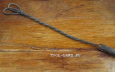
The main difference between a pulse soldering iron is the method of heating its tip, which is a copper wire bent in an arc (like the letter “U”), through which a high-power electric current is passed, necessary to achieve the required temperature.

Heating copper wire in the form of a sting
The power supply of such a soldering iron must provide an output voltage of 1-2 V and a current of 25-50 A. Until recently, a conventional transformer was actively used for these purposes, in which the secondary winding is made in the form of several turns of a copper bus of a relatively large cross-section (several times larger, than the cross-section of the tip wire, in order to avoid heating the winding itself during operation).
Also, the conductive bars that serve as a tip holder must have a large cross-section, so the power supply is placed in the body of a pulse soldering iron, which, due to its revolving handle, resembles a pistol.

Typical shape of an industrial pulse soldering iron
But the considerable dimensions and noticeable weight of the step-down transformer make working with a soldering iron inconvenient, so recently switching power supplies have begun to be used, which are much smaller and lighter.
Current sources used to power pulsed soldering irons
Pulse soldering irons also have this name because of the improvement and miniaturization of power supplies used in these tools, which use an electronic circuit for converting high-frequency voltage pulses, although a regular one can also be used a step-down transformer suitable power.
Therefore, when creating a pulse soldering iron with your own hands, you need to decide which power supply will be used - with a step-down transformer, or electronic. The advantage of the first option is the extremely simple electrical circuit - the terminals of the secondary winding are directly connected to the conductive busbars.

An example of a homemade soldering iron with a step-down transformer
Disadvantages include the dimensions and weight of the device, as well as noticeable vibration during operation. In addition, the primary winding very often burns out due to unstable voltage and frequent overloads, and it is impossible to independently rewind it without special equipment and the appropriate winding wire.
Therefore, many radio amateurs, when repairing a failed pulse soldering iron based on a step-down transformer, use suitable electronic power supply. replacing the secondary winding.

Burnt-out step-down transformer in an industrial soldering iron

The bulky transformer is replaced with a miniature electronic board
The process of converting a step-down transformer
When making a pulse soldering iron, you can use an existing step-down transformer to power it, which can be with any type of magnetic circuit, the main thing is that it is suitable for power in the range of 50-150 W.
The primary network winding is left unchanged, and the secondary is removed by disassembling the transformer. Since current is of decisive importance for heating the soldering iron tip, the exact calculation of the number of turns can be neglected, concentrating efforts on achieving the maximum possible cross-sectional area of the winding busbar.
As a rule, two turns of a copper busbar or braided flexible copper wire with a cross-section of 6-10 mm² will be sufficient, which must be positioned in such a way that they do not short-circuit with each other and the transformer core.

Copper busbar in the form of a secondary winding
In the case of using a copper bus as a winding, its terminals will serve as a tip holder.

The continuation of the winding is the tip holder
The elastic bus should be wound carefully so as not to damage the primary winding, after which it should be checked for breaks and short circuits.
Remaking an electronic transformer
Creating a pulse soldering iron with their own hands from scratch, or using a ready-made case with holders, many radio amateurs use the existing electronic power supply for 12V halogen lamps with a power of 50-150W as a transformer, while also remaking the secondary winding.

Electronic transformer (switching power supply for halogen lamps)
Since no other changes to the device are required, a typical electrical circuit diagram of a switching power supply is given only as an example, without analyzing the functions of the elements and describing the operating principle.

Pulse transformer in the diagram, subject to alteration
In this case, you need to remember that to achieve the required voltage in a pulse transformer, smaller magnetic core dimensions and fewer turns are required, so one turn may be enough to remake the secondary winding.

One output turn on the toroidal magnetic core of the pulse transformer
If the existing bus or flexible wire has an insufficient cross-section, it can be increased by connecting the turns of the windings in parallel.

Connecting the leads of parallel turns to the tip holder

Parallel turns of flexible braided copper stranded wire
Since the old secondary winding can be removed without disassembling the transformer, and a new one can be created simply by inserting one turn into the voids between the insulation and the magnetic circuit, the process of remaking a switching power supply is not too difficult even for a novice craftsman.
Making a soldering iron tip
As a soldering iron tip, you need to use copper wire with a diameter of 1-2 mm, connecting it to the holders using bolted or ready-made collet connections.

Bolt fastenings of the sting on the plates
More accurately, the thickness of the wire is determined experimentally - by the speed with which the temperature of the soldering iron reaches the operating range - the thinner the tip wire, the faster it will heat up. But on the other hand, too high a temperature will make the soldering process impossible and will lead to rapid wear and even burnout of the wire.
By increasing the cross-section of the wire, it is necessary to achieve an acceptable time (4-8 seconds) for heating the tip and preventing it from overheating. It must be remembered that with an increase in the cross-sectional area of the tip wire, the power consumption and heating of the secondary winding of the transformer increase.
Therefore, having selected the required diameter of the tip wire and tested a homemade soldering iron in operation, having carried out the soldering process several times, you need to check the heating of the secondary winding - it should not heat up too much, much less get hot - otherwise the transformer may overheat, which will lead to burnout of the primary winding and ignition isolation.
For ease of operation, a light bulb or LED is often connected, which turns on synchronously and illuminates the soldering area.

A bright LED turns on synchronously with the soldering iron, illuminating the soldering area
Advantages and disadvantages
Having picked up the necessary parts on the market, or disassembled other devices, having minimal skills in radio engineering, you can assemble such a soldering iron with your own hands, adding to your arsenal a tool that will compare favorably in the following parameters:
- Economical – no electricity is used when the tool is idle;
- Safety - the tip is always inoperative cold. which eliminates skin burns, fires of objects and melting of the power cord insulation due to accidental touch;
- Convenient to repair - the absence of a heating element prevents it from burning out, and making and replacing the tip is much simpler than that of a conventional soldering iron, where it often gets stuck.
The disadvantages include its considerable size and significant weight, which requires some physical effort and causes hand fatigue after prolonged work. Therefore, many radio amateurs separate the electronic circuit and the pulse transformer, making the instrument lighter.

Electronic circuit and pulse transformer are separated

Transformer separated from the circuit
A soldering iron is the main “weapon” of an electronics engineer. You can make a fairly powerful, compact and lightweight soldering iron with your own hands. This homemade soldering iron differs from the devices known to us in that there is no tip heater, or rather, there is one, but the operating principle is completely different. Conventional soldering irons use a fairly simple and trouble-free principle for heating the tip - a nichrome spiral. The spiral plays the role of a heating element, the heat of which is transferred to the sting. We are all used to waiting for a while until the soldering iron warms up - this is sometimes very annoying if the work is urgent.
How to make a pulse soldering iron
The soldering iron we are going to make is Warms up in just 5 seconds, during this time he acquires the ability to melt tin. The basis of such a soldering iron is a switching power supply, which uses a control circuit (ballast) from a 40-watt LDS. The ballast has a network filter, consisting of chokes for filtering high-frequency interference and capacitors for filtering network low-frequency interference. The board also has a mains fuse and a thermistor.
The operating principle of a pulse soldering iron is based on a short circuit of the secondary winding of the transformer, as a result of which heating occurs. The soldering iron tip is also part of the secondary winding.
The secondary winding consists of a copper busbar with a diameter of 3.5 mm; in my case, two wires of 1.7 mm each were used. The winding consists of only one turn.
The tip is a copper or nickel wire with a diameter of 1.5-2 mm connected directly to the secondary winding of the transformer.
Transformer - ferrite ring from a pulse converter (rings from electronic transformer blocks can be used). The dimensions of the ring are not critical, the main thing is to place the windings. The primary winding (network) consists of 100-120 turns of 0.5 mm wire, stretched evenly across the entire ring.
Radio amateurs are making more and more equipment for their work independently. The pulse soldering iron was no exception. You can make it yourself.
Experienced radio amateurs well remember the domestic instantaneous heating pulse soldering iron “Moment” with a light bulb near the heating element.
This technology has not been forgotten today. In radio stores you can buy a soldering gun for a reasonable price. What if it's free? Easily! You can assemble such a device from elementary parts that are available in the workshop of any homemade product.

First, let's look at the design of a soldering iron that operates on the pulse principle.
The working tip is a piece of copper wire with a diameter of 1-3 mm (depending on the parts that need to be soldered). The working tip is heated by passing a large current through it at a minimum operating voltage.
The principle of short circuit, or spot welding. Another design element is a 50 Hz mains voltage converter into a high-frequency one, with a frequency of tens of kilohertz. The secondary winding is connected to the current collectors of the working tip.
The device is quite economical. Mainly due to short term use. The main difference from a regular soldering iron is that it does not need to be kept on all the time to maintain operating temperature. The tip heats up within a few seconds. Therefore, most of the time the device does not consume electricity.
How to make your own “Moment” soldering iron from a house-saving lamp
It is necessary to find used components from old household electrical appliances:
- Converter (ballast) from a fluorescent lamp. Enough power 40 W;
- Working transformer;
- Copper wire 2-3 mm in diameter;
The case, or rather the manufacturing technology, is not important.
Device diagram:

In fact, everything that we see on the circuit diagram to the left of transformer Tr1 is part of the ballast from the energy-saving lamp. The device is complete; there is no need to modify it or change components.
The characteristics of the converter are quite suitable for a medium-power pulsed soldering iron. The safety of the design is enhanced by a standard fuse and overheating control using a thermistor.
The circuit turns out to be compact and can be placed in any housing.

The working transformer is made independently. A ferrite ring from a broken electronic transformer is suitable for this. The size must be sufficient to accommodate the windings. We wind the primary from 0.5 mm wire. The number of turns is 100-120.
Popular: How to solder without a soldering iron, or how to replace it

The secondary (power) winding is made of wire with a cross-section of 3-3.5 squares. We make one turn. A soldering iron tip made of copper or nichrome wire 1.5 - 2 mm is attached directly to it.
IMPORTANT! The thickness of the secondary winding must be greater than the thickness of the tip.
A pulsed soldering iron made from an energy-saving lamp is ready. All that remains is to come up with a convenient housing for it, install a switch, and you can quickly repair electrical appliances.
Pulse soldering iron from a Chinese transformer
It is necessary to find a working 12 volt switching power supply, or one with a burnt-out secondary winding. Any Chinese device with more or less adequate components will do.

We remove the circuit from the case and check the serviceability of the parts and installation. We leave the converter untouched; to remake it, you only need to change the transformer configuration.

Carefully remove the secondary winding of the transformer. To make a new one, we need copper wire with a cross section of 1.5 - 3 square mm. If the cross-section is small, fold the wire in half. There is nothing wrong with such a solution, the overall cross-section is important to us, it must be at least 3 squares.
The winding consists of one incomplete turn. Carefully thread the resulting winding into the transformer body, having previously bent it like a hairpin.

We solder the transformer back to the control board, and fix the new secondary winding with any dielectric glue, for example, cold welding.

The most important thing is safety precautions when working with a soldering iron, so we return the circuit back to the case.

A wooden handle from a regular soldering iron is perfect as a handle. Options are possible, given the overall compactness of the device. We install a non-fixed switch in the handle.
IMPORTANT! The operation of a pulse soldering iron is based on a short circuit of the secondary winding; prolonged heating can lead to a fire and destruction of the transformer.
Therefore, a latched starter is not acceptable.
We assemble the device completely, all that remains is to install the clamps for the tip.

In many stores today you can buy a soldering iron for reasonable money. Yes, and you can assemble such a device with your own hands from parts that almost everyone has in their home. But it’s always more interesting to make something yourself than to buy something ready-made. In this article, we’ll look at what a pulse soldering iron is, the differences from a regular one, and the easiest way to make one yourself.
Pulse soldering iron: device design
Pulse soldering iron required for installation (dismantling) of elements of electrical and electronic products. The heating element is a tip, which is made of copper wire (diameter 1-3 mm) coated with other metals. The tip is heated by passing a low voltage current through it. The soldering iron consumes little electricity, since current passes through the tip only during soldering. The device has a mains voltage converter with a frequency of 18−40 kHz. The secondary (power) winding is connected to the current collectors of the tip.
The main difference between a pulsed soldering iron and a regular soldering iron is that it does not need to always be kept on to maintain the temperature. The tip is heated within a few seconds. It is precisely because of this that the device does not consume electricity most of the time.
Types of soldering irons:
- Induction;
- Ceramic;
- Pulse;
- Rechargeable.
DIY soldering iron: simple assembly diagrams
Before making a soldering iron with your own hands, you should determine what exactly it will be used for and what materials are available at home.
“Moment” from a house-saving lamp
Components of the device:

The characteristics of the converter are suitable for a medium-power soldering iron. The safety of the device is enhanced by a standard fuse and overheating control on the thermistor. The circuit is very compact and can be placed in any housing.
The transformer is made independently. You can use a ferrite ring from a broken electrical transformer. The primary winding must be wound from 0.5 mm wire, the number of turns is 100-120. And the power one should be made of wire with a cross-section of 3 to 3.5 square meters. mm. You need to make one turn. We attach a tip made of nichrome or copper wire (1.5 - 2 mm) to it. The thickness of the last winding should be greater than the thickness of the tip. Next, you need to come up with a body for the device, make a switch, and the device is ready.
From a Chinese transformer
For production you need either a working twelve-volt power supply, or one with a burnt-out secondary winding. Any Chinese device will do just fine.
It is necessary to remove the circuit from the case and check the serviceability of the parts. We do not touch the converter, since we only need to change the appearance of the transformer. Next, we remove the secondary winding and make a new one from copper wire (the cross-section should be 1.5-3 sq. mm). If the cross-section is small, fold the wire in half. What is important is the overall cross section, which will be at least three squares. The winding is equal to one incomplete turn. Then, carefully thread it into the transformer body, first bending it like a hairpin. The transformer is soldered to the control board, and the power winding must be fixed with dielectric glue (for example, cold welding). Next, we insert the circuit into the case.
A wooden handle from a regular soldering iron can be used as a handle. Other options are possible, given the compactness of the device as a whole. We insert a non-fixed switch into the handle. The operation of a pulse device is based on a short circuit of the secondary winding, as a result of which prolonged heating can lead to destruction of the transformer and fire. For this reason, a fixed starter is not permitted. Next, you need to assemble the device completely and install the clamps for the tip (for example, inserts from a terminal box for wiring). This device is very compact and easy to use for small soldering jobs. Thanks to the replaceable tip, you can change its appearance.
These options are only a small fraction among the variety of schemes for manufacturing pulsed devices.
 It is important to understand the principle of operation:
- A device that converts electricity into high-frequency voltage;
- Step-down transformer, designed only for high frequency;
- The secondary winding, which forms a closed ring with a loop-shaped tip.
A pulse soldering iron is a reliable and economical device, and if you do it yourself, it’s also practically free. And in most cases, even a novice electrician can assemble a homemade instrument without having professional knowledge of working with radio equipment.
A standard soldering iron has a heating device that consists of nichrome wire. The heat from this wire is released to the copper tip. It's easy even at home. Its only disadvantage is that you have to wait a long time until it heats up to the desired temperature. But in a pulse soldering iron there is no such drawback. It received this name because its tip heats up in about 5 seconds or even faster. Most often, the soldering iron tip is made from a piece of curved copper, which has a diameter of 1 or 2 millimeters.
The pulse soldering iron tip heats up in just 5 seconds.
Pulse soldering iron and how to make it yourself
The scheme according to which it is arranged is much more complicated than usual. To make such a soldering iron with your own hands, you need an electronic type transformer. Several halogen lamps are connected to it, which have an output voltage of 12 volts. Then this transformer needs some work. Its essence is that it requires removal of the secondary winding and additional winding in the form of 1-2 turns of copper wire 1 millimeter thick. The finished, already modified winding is placed under the housing, which looks like a pistol with a trigger. This trigger will turn on the soldering device. Another change is that in the place where the barrel of the resulting pistol is located, a dielectric-type stand is placed, with a copper bracket attached to it, which is called the “sting.” Such a bracket is similar to medical tweezers, with voltage supplied to its edges through a switch with a button. To modify the resulting tool, an LED light bulb is connected to it.

With the help of a lamp it will be much easier to solder. While using such a tool, you need to be careful about one thing. You should not keep the tip in the “on” position for too long, in which heating occurs. This will help avoid damage to its electrical circuit.
Components of a pulse soldering iron:
- electronic type transformer;
- halogen bulbs;
- copper tip;
- LEDs.
Return to contents
Self-production of a microcircuit soldering iron
The difference between microcircuit soldering irons and devices of other types is that there is absolutely no tolerance for overheating of its electronic component.
The only thing is that it is necessary to have special protection devices that protect the microcircuits from damage. In such soldering irons, the device that acts as a power supply unit is best used as follows. It must have an adjustable output voltage ranging from 0 to 15 volts. The element that will cause heating can be an MLT resistor with a nominal value of about 8 Ohms and a power of 0.5 Watts; sometimes ultrasound is used for this.
To make such a resistor, you need to remove one leg and make a hole (using drilling) in the place where it is attached, having a thickness of 1.1 millimeters. To maintain safety, you need to use a piece of mica to protect its end from touching the internal cavity of the resistor bowl when the tip is inserted. This creates a soldering iron for microcircuits. It is best to attach an already “modified” soldering iron to the end of its body with any broken handle in which the rod has run out. This is done using a special textolite having two sides, or a mounting strip. Thanks to this, the resistor-type heater receives voltage from the power supply unit. The tool is ready.