Educational program on soldering. Soldering iron with temperature control Soldering iron operating temperature
Soldering with a soldering iron is one of the most common and simplest soldering methods, but it has two significant limitations. Firstly, a soldering iron can only be soldered with low-melting (soft) solders, and secondly, it cannot (or, in any case, is difficult) to solder massive parts with a large heat sink - due to the impossibility of heating them to the melting temperature of the solder. The last limitation is overcome by heating the part to be soldered with an external heat source - a gas burner, electric or gas stove, or some other method - but this complicates the soldering process.
Before you solder with a soldering iron, you need to get everything you need. The main tools and materials without which soldering is impossible include the soldering iron itself, solder and flux.
Soldering irons
Depending on the heating method, soldering irons can be “conventional” - electric (with a spiral or ceramic heater), gas (with a gas burner), hot-air (heat is transferred by air flow), and induction. Massive hammer soldering irons can be heated not only with electricity, but also in the old fashioned way - with an open flame.
You can learn how to use such a soldering iron from the descriptions of the technology of tin work, which is where they were used most often. Nowadays, electric soldering irons are usually used due to their availability and ease of use. But the first soldering irons were heated over an open flame.

The main parameter by which a soldering iron is selected is its power, which determines the amount of heat flow transferred to the parts being soldered. Devices with a power of up to 40 W are used for soldering electronic components. Thin-walled parts (with a wall thickness of up to 1 mm) require a power of 80-100 W.


For parts with a wall thickness of 2 mm or more, soldering irons with a power above 100 W will be needed. These are, in particular, electric hammer soldering irons that consume up to 250 W and higher. The most energy-intensive soldering irons include, for example, the Ersa Hammer 550 hammer soldering iron with a power of 550 W. It is capable of heating up to a temperature of 600°C and is designed for soldering particularly massive parts - radiators, machine parts. But it has an inadequate price.

In addition to the massiveness of the part, the required power of the soldering iron is also affected by the thermal conductivity of the metal being soldered. As it increases, the power of the device and its heating temperature must be increased. When soldering parts made of copper with a soldering iron, it must be heated more than when soldering a part of the same mass, but made of steel. By the way, when working with copper products, a situation may arise when, due to the high thermal conductivity of the metal, during soldering, desoldering of previously completed areas will occur.
Solders
When soldering with electric soldering irons, low-temperature tin-lead (POS-30, POS-40, POS-61), tin-silver (PSr-2, PSr-2.5) or other solders and pure tin are used. The disadvantages of solders containing lead include the harmfulness of the latter, and the advantages include better soldering quality than that of lead-free solders. Pure tin is used for soldering food utensils.
Fluxes
It is generally accepted that tin, silver, gold, copper, brass, bronze, lead, and nickel silver can be soldered well. Satisfactory - carbon and low-alloy steels, nickel, zinc. Poor - aluminum, high-alloy and stainless steels, aluminum bronze, cast iron, chrome, titanium, magnesium. However, without disputing these data, we can say that there is no poorly soldered metal, there is poor preparation of the part, incorrectly selected flux and incorrect temperature conditions.Selecting the right flux for soldering means solving the main problem of soldering. It is the quality of the flux that primarily determines the solderability of a particular metal, the ease or difficulty of the soldering process itself, and the strength of the connection. The flux must correspond to the material of the products being soldered - in its ability to destroy its oxide film.
Acidic (active) fluxes, such as “Soldering Acid” based on zinc chloride, cannot be used when soldering electronic components, as they conduct electricity well and cause corrosion, however, due to their aggressiveness, they prepare the surface very well and are therefore indispensable when soldering metal structures, and the more chemically resistant the metal, the more active the flux should be. Residues of active fluxes must be carefully removed after soldering is completed.
Effective fluxes for soldering steel are an aqueous solution of zinc chloride, soldering acids based on it, and LTI-120 flux. You can use other, stronger fluxes, of which there are plenty on the market.

The main difference between soldering stainless steels with a soldering iron and soldering carbon and low-alloy steels is the need to use more active fluxes, which are required to destroy the chemically resistant oxides with which stainless steels are coated. As for cast iron, it needs to be soldered with high-temperature soldering, and, therefore, an electric soldering iron is not suitable for this purpose.
For stainless steel, phosphoric acid is used. Specialized fluxes, such as F-38, also cope well with chemically resistant oxide films.

For galvanized iron, you can use a composition containing rosin, ethyl alcohol, zinc chloride and ammonium chloride (LK-2 flux).
Auxiliary materials and devices
You can do without some devices and materials used for soldering, but their presence makes the work much more convenient and comfortable.Soldering iron stand serves to ensure that the heated soldering iron does not touch the table or other objects. If it does not come with a soldering iron, you can purchase it separately or make it yourself. The simplest stand can be made from a thin sheet of tin, cutting grooves in it for storing tools.

Wet viscose or foam rubber sponge, placed in a socket to prevent falling out, it is much more convenient to clean the tip of the soldering iron than with a regular cloth. Brass shavings can also serve for the same purposes.

You can remove excess solder from the surface of parts using special suction or braids. The first one, in appearance and design, resembles a syringe equipped with a spring. Before use, it must be cocked by recessing the rod head. By bringing the nose to the molten solder, the spring is released by pressing the release button. As a result, excess solder is drawn into the removal head.

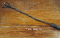
It is a braid of fluxed thin copper wires. By placing its end on the solder and pressing it on top with a soldering iron, thanks to capillary forces you can collect all the excess solder in it like a blotter. The tip of the braid, saturated with solder, is simply cut off.


A very useful device is called third hand(Third-Hand Tool). When working with a soldering iron, sometimes there are catastrophically “not enough hands” - one is occupied with the soldering iron itself, the other with the solder, but you still need to hold the soldered parts in a certain position. The “third hand” is convenient because its clamps can be easily installed in any position relative to each other.

Soldering holder "Third hand"
The parts being soldered are heated to high temperatures; touching them can cause you to get burned. Therefore, it is desirable to have various clamping devices that allow the manipulation of heated parts - pliers, tweezers, clamps.
Preparing the soldering iron for use
When you turn on the soldering iron for the first time, it may start to smoke. There is nothing wrong with this, the oils used to preserve the soldering iron simply burn out. You just need to ventilate the room.Before using a soldering iron, you need to prepare its tip. Preparation depends on its original form. If the tip is made of bare copper, the tip can be forged into a screwdriver shape, this will seal the copper and make it more resistant to wear. You can simply sharpen it with sandpaper or a file, giving it the required shape - in the form of a sharp or truncated cone with a different angle, a tetrahedral pyramid, an angular bevel on one side. Nickel metal coatings are used to protect copper from oxidation. If the soldering iron has such a coating, then it cannot be forged or sharpened to avoid damaging the coating layer.
There is a standardized range of tip shapes, but you can, of course, use any shape suitable for the particular job.

When soldering massive parts, the contact area between the soldering iron and the part should be maximum to ensure better heat transfer. In this case, angular sharpening of a round rod (2 in the photo above) is considered the best. If you plan to solder small parts, then a sharp cone (4), knife or other shapes with small angles are suitable.
Instructions for working with a soldering iron that has an uncoated copper tip contain one mandatory requirement - tinning the “tip” of the new soldering iron in order to protect it from oxidation and wear. Moreover, this should be done during the first heating, without delay. Otherwise, the “tip” will be covered with a thin layer of scale, and the solder will not want to stick to it. This can be done in different ways. Warm up the soldering iron to operating temperature, touch the “tip” to the rosin, melt the solder on it and rub the solder on a piece of wood. Or wipe the heated tip with a rag moistened with a solution of zinc chloride, melt solder on it and rub it over the tip with a piece of ammonia or rock table salt. The main thing is that as a result of these operations, the working part of the tip is completely covered with a thin layer of solder.
The need to tin the tip is caused by the fact that the flux gradually corrodes, and the solder dissolves the tip. Due to loss of shape, the tip has to be sharpened regularly, and the more active the flux, the more often, sometimes several times a day. For nickel-plated tips, nickel blocks access to copper, protecting it, but such tips require careful handling, they are afraid of overheating, and it is not a fact that the manufacturer has made a sufficiently high-quality coating, for which they require an overpayment.
Preparing parts for soldering
Preparing parts for soldering involves performing the same operations regardless of what type of soldering (low-temperature or high-temperature) is performed, and what heating source (electric or gas soldering iron, gas torch, inductor or something else) is used.First of all, this is cleaning the part from dirt and degreasing. There are no special subtleties here - you need to use solvents (gasoline, acetone or others) to clean the part from oils, fats, and dirt. If there is rust, it must be removed by any suitable mechanical method - using an emery wheel, wire brush or sandpaper. In the case of high-alloy and stainless steels, it is advisable to treat the edges being joined with an abrasive tool, since the oxide film of these metals is particularly strong.
Soldering temperature
The heating temperature of the soldering iron is the most important parameter; the quality of soldering depends on the temperature. Insufficient temperature manifests itself in the fact that the solder does not spread over the surface of the product, but forms a lump, despite the preparation of the surface with flux. But even if the soldering was successful in appearance (the solder melted and spread over the joint), the soldered joint turns out to be loose, matte in color, and has low mechanical strength.The soldering temperature (temperature of the parts being soldered) should be 40-80°C higher than the melting temperature of the solder, and the heating temperature of the tip should be 20-40°C higher than the soldering temperature. The last requirement is due to the fact that when it comes into contact with the parts being soldered, the temperature of the soldering iron will decrease due to heat dissipation. Thus, the heating temperature of the tip should exceed the melting temperature of the solder by 60-120°C. If a soldering station is used, the required temperature is simply set by the regulator. When using a soldering iron without temperature control, its actual value, when using rosin as a flux, can be assessed by the behavior of the rosin when touched by the soldering iron. It should boil and release abundant steam, but not burn instantly, but remain on the tip in the form of boiling drops.
Overheating the soldering iron is also harmful; it causes combustion and charring of the flux until it activates the junction surface. Overheating is indicated by a dark film of oxides that appears on the solder located at the tip of the soldering iron, as well as by the fact that it does not stay on the “tip” and flows off it.
Soldering technique with a soldering iron
There are two main methods of soldering with a soldering iron:- Supply (drain) of solder onto the parts to be soldered from the tip of the soldering iron.
- Supplying solder directly to the parts to be soldered (to the pad).
With any method, you must first prepare the parts for soldering, install and secure them in their original position, heat the soldering iron and moisten the joint with flux. Further steps differ depending on which method is used.
When feeding solder from a soldering iron, a certain amount of solder is melted on it (to keep it on the tip) and the “tip” is pressed against the parts being soldered. In this case, the flux will begin to boil and evaporate, and the molten solder will move from the soldering iron to the soldering joint. The movement of the tip along the future seam ensures the distribution of solder along the joint.

Solder on the jelly may be sufficient if the tip has simply acquired a metallic sheen. If the shape of the tip has noticeably changed, there is too much solder.

When applying solder directly to a junction, use a soldering iron to first heat the parts to soldering temperature, and then apply solder to the part or to the joint between the soldering iron and the part. As the solder melts, it will fill the joint between the parts being soldered. You should choose exactly how to solder with a soldering iron - the first or second method - depending on the nature of the work being performed. The first method is better for small parts, the second for large parts.
The basic requirements for high-quality soldering include:
- good heating of the soldering iron and parts being soldered;
- sufficient amount of flux;
- entering the required amount of solder - exactly as much as required, but no more.
Here are some tips on how to solder correctly with a soldering iron.
If the solder does not flow, but is smeared, it means that the temperature of the parts has not reached the required values, you need to increase the heating temperature of the soldering iron or use a more powerful device.
There is no need to add too much solder. High-quality soldering requires the presence of a minimum sufficient amount of material in the joint, at which the seam turns out to be slightly concave. If there is too much solder, there is no need to try to attach it somewhere at the joint; it is better to remove it with suction or braiding.
The quality of the junction is indicated by its color. High quality - the solder has a bright shine. Insufficient temperature makes the structure of the junction grainy and spongy - this is a definite defect. Burnt solder looks dull and has reduced strength, which in some cases may be quite acceptable.
When using active (acidic) fluxes, be sure to wash off their residues after soldering - with some detergent or ordinary alkaline soap. Otherwise, there is no guarantee that after some time the connection will not be destroyed by corrosion from remaining acids.
Tinning
Tinning - coating the metal surface with a thin layer of solder - can be either an independent, final operation, or an intermediate, preparatory stage of soldering. When this is the preparatory stage, successful tinning of the part in most cases means that the most difficult part of the soldering job (joining the solder to the metal) is done; soldering the tinned parts to each other is usually no longer difficult.Wire tinning. Tinning the ends of electrical wires is one of the most common operations. It is carried out before soldering the wires to the contacts, soldering them together, or to ensure better contact with the terminals when connecting with bolts. It is convenient to make a ring from a tinned stranded wire, which ensures ease of attachment to the terminal and good contact.
Wires can be single-core or stranded, copper or aluminum, varnished or not, clean new or acidified old. Depending on these features, their servicing differs.
The easiest way to tin is single-core copper wire. If it is new, then it is not covered with oxides and tins even without stripping, you just need to apply flux to the surface of the wire, apply solder to the heated soldering iron and move the soldering iron along the wire, slightly turning the wire. As a rule, tinning proceeds without problems.


If the conductor does not want to tinker - due to the presence of varnish (enamel) - regular aspirin helps. Knowing how to solder with a soldering iron using an aspirin tablet (acetylsalicylic acid) can be very useful in some cases. You need to put it on a board, press the conductor to it and heat it for a few seconds with a soldering iron. At the same time, the tablet begins to melt, and the resulting acid destroys the varnish. After this, the wire usually tins easily.
If there is no aspirin, vinyl chloride insulation from electrical wires, which when heated, releases substances that destroy the varnish coating, also helps to remove the varnish that interferes with tinning from the surface of the conductor. You need to press the wires to a piece of insulation with a soldering iron and drag it several times between the insulation and the soldering iron. Then tin the wire as usual. When removing varnish using sandpaper or a knife, cuts and breaks of thin wire strands are common. When stripped by firing, the wire may lose strength and break easily.
It should be taken into account that melted polyvinyl chloride and aspirin release substances harmful to health into the air.
Also, for varnished (enamel) wires, you can purchase a special flux that removes the varnish.

New stranded copper wire can be tinned just as easily as solid copper wire. The only peculiarity is to rotate it in the direction in which the wires will twist and not unwind.
Old wires may be coated with oxides that prevent tinning. The same aspirin tablet will help to cope with them. You need to untwist the conductor, put it on aspirin and heat it for a few seconds with a soldering iron, moving the conductor back and forth - and the tinning problem will disappear.
To tinning an aluminum wire, you will need a special flux - for example, the one called “Flux for soldering aluminum”. This flux is universal and is also suitable for soldering metals with a chemically resistant oxide film - stainless steel, in particular. When using it, you just need to remember to clean the connection from flux residues afterwards to avoid corrosion.

If, when tinning the wires, excess surf has formed on them, you can remove it by placing the wire vertically, end down, and pressing a heated soldering iron to its end. Excess solder will flow from the wire onto the soldering iron.
Tinning a large metal surface
Tinning the surface of the metal may be necessary to protect it from corrosion or for subsequent soldering of another part to it. Even if a completely new sheet is tinned, which looks clean on the outside, there can always be foreign substances on its surface - preservative grease, various contaminants. If a sheet covered with rust is tinned, then it needs cleaning all the more. Therefore, tinning always begins with thorough cleaning of the surface. Rust is cleaned off with emery cloth or a wire brush, fats and oils are removed with gasoline, acetone or another solvent.Then, using a brush or other tool that matches the flux, flux is applied to the surface of the sheet (this may not be a paste-like flux as in the photo below, but, for example, a solution of zinc chloride or another active flux).

A soldering iron with a relatively large flat tip surface is heated to the required temperature and solder is applied to the surface of the part. It is advisable that the soldering iron power be about 100 W or higher.

Then apply the soldering iron to the solder on the part with the largest plane and keep it in this position. The heating time of the part depends on its size, the power of the soldering iron and the contact area. The achievement of the required temperature is indicated by boiling of the flux, melting of the solder and its spreading over the surface. The solder is gradually distributed over the surface.

After tinning, the metal surface is cleaned of flux residues with alcohol, acetone, gasoline, and soapy water (depending on the chemical composition of the flux).

If the solder does not spread over the metal surface, this may be due to poor cleaning of the surface before tinning, poor heating of the metal (due to insufficient soldering iron power, small contact area, insufficient time to warm up the metal of the part), or a dirty soldering iron tip. Another reason may be the wrong choice of flux or solder.

Tinning can be carried out by applying (draining) solder from a soldering iron and distributing it with a “tip” over the surface, or by supplying solder directly to the pad - the solder melts upon touching the heated metal of the part.
Overlapping sheet metal soldering
When repairing car bodies, all kinds of tin work, there is a need for overlay soldering of sheet metal. There are two ways to solder sheet parts overlapping each other - by pre-tinning them, or by using soldering paste containing solder and flux.In the first case, the overlapping areas of parts after mechanical cleaning and degreasing are pre-tinned. Then the parts of the connection are applied to each other with tinned surfaces, fixed with clamping devices and heated with a soldering iron from different sides to the melting temperature of the solder. Evidence of successful soldering is the flow of molten solder from the gap.
In the second method, after preparing the parts, the contact area of one of the parts is covered with solder paste. Then the parts are fixed in the desired position, tightened with clamps and, as in the first case, the seam is heated with a soldering iron on both sides.
When purchasing solder paste, you need to pay attention to its purpose, because... Many solder pastes are designed for soldering electronics and do not contain active fluxes that allow you to solder steel.


When using the content of this site, you need to put active links to this site, visible to users and search robots.
Soldering temperature is an important point in the solder’s work, on which the quality of the metal connection depends. This indicator should be higher than the similar indicator of complete melting of tinol. In some cases, the indicator may be between the liquidus line and the solidus line.
Based on theory, the solder must be completely melted before it fills the gap and is distributed in the joint under the influence of capillary forces. In this regard, the liquidus temperature of tinol can be the lowest used for a procedure such as high-temperature soldering. In turn, all parts must be heated to this temperature or higher.
You cannot be sure that all internal and external parts of the parts are heated only to a given temperature. The heating rate, location, mass of metal parts, as well as the coefficient of thermal expansion of the metal being soldered are all factors that determine the heat distribution in the part.
Under conditions of rapid local heating of parts, the temperature distribution is uneven, the temperature of the outer surfaces is significantly higher than the inner ones. During slow heating and uniform heat distribution, the distribution of thermal energy in the solder joint occurs more evenly.
Diffusion and dissolution of tinol during soldering
During wetting of the metal being joined with molten solder, dissolution of the base metal by tinol or diffusion of tinol components into the base metal may occur. In addition, diffusion is most likely to form if the tinol and the base metal are similar in chemical composition.
The following factors may influence dissolution and diffusion:
- Material joining temperature;
- Soldering duration;
- The geometry of the metal being joined, since it determines the area of the base material exposed to tinol;
- Chemical composition.
In rare cases, during soldering, due to local diffusion of tinol between the grains of the base material, material spreading occurs, depending on internal stresses. Excessive diffusion of tinol in the base metal is likely to affect the mechanical and physical properties of the metal.
Thus, the thin parts of the base material are the most vulnerable area of the solder joint. In this place, due to erosion, through sinks can form. It is worth noting that the dissolution of the base metal with tinol changes its liquidus temperature, thereby leading to insufficient filling of the gap between the parts.
To reduce diffusion or dissolution, there are several alloys that are used as tinols. Solders acquire a liquid consistency when the temperature reaches below the effective liquidus temperature. Thanks to solder of this composition, high-temperature soldering is also carried out successfully in those circumstances when the temperature of the metal connection has not reached the liquidus line.
SMD component connection temperature
Bottom heating makes it possible to reduce heat transfer from the component to the SMD board, thereby reducing the required temperature of the soldering tool. When using air methods for replacing components, bottom heating can reduce or completely eliminate warping of the SMD board, which may well occur due to one-sided heating by hot air.
In addition, printed circuit boards made on ceramics require gentle preheating before the soldering procedure due to the sensitivity of these materials to temperature changes.
Based on the method of supplying thermal energy, we can distinguish infrared and convection bottom heaters. The first devices often consist of several quartz lamps, which have a pronounced red glow. Regarding convection devices, they can work by using forced convection.
The SMD components under consideration are quite fragile, and under conditions of vibration instability (mechanical shocks) they can crack. Another disadvantage of SMD components is their intolerance to overheating during soldering, which often causes microcracks that are almost impossible to notice. The most unpleasant thing, perhaps, in this matter is that you find out about cracks in SMD components during operation. You can check for cracks in SMD parts using an ordinary multimeter.
Thus, you can connect SMD parts using a soldering station, as well as a soldering iron. A certain part of solders claim that it is easier to solder components using a soldering station with a stabilized temperature. However, if there is no soldering station, you can resolve the issue using a soldering iron, turning it on using the regulator. It is worth noting that without a regulator on a conventional soldering iron, the temperature of its tip (tip) reaches a temperature of 400 degrees. The C. indicator when working with SMD components should be 260-270 g. WITH.
The optimal heating temperature of the soldering iron tip, as well as the required power during manual soldering, are indicators that depend on the design features of the soldering iron and the task it performs. When working with lead-free tubular solders, which have a melting point of about 217-227 degrees. C, the minimum heating value of the soldering iron tip is 300 g. WITH.

During soldering, it is necessary to avoid in every possible way excessive overheating of the soldering iron tip, as well as prolonged exposure of the tip to the metal. In most cases, when working with lead-free solders and traditional tinols, it is most suitable to heat the soldering iron tip to a temperature of 315-370 degrees. WITH.
In certain situations, excellent results when soldering SMD components can be obtained during short-term heating (the duration of exposure of the soldering iron tip is up to 0.5 seconds), as well as when heating the soldering iron tip to a value from 340 to 420 degrees. WITH.
The procedure for soldering SMD components
The procedure for soldering SMD components:
- First, remove one of the contact pads. To do this, apply a sufficient amount of tinol to further form the fillet.
- Next comes the installation of the SMD component on the gearbox.
- The next step is to hold the SMD component with tweezers, and at the same time bring the soldering iron tip, thereby ensuring simultaneous contact of the soldering iron tip with the output of the SMD component, as well as the tinned CP.
- Perform short-term soldering for 0.5-1.5 seconds. Regarding the tip of the device, it should be retracted.
- Next, high-temperature soldering of the second terminal is performed: by bringing the tip of the device, you ensure simultaneous contact of the tip with the terminal and the gearbox.
- Next, from the side opposite to the soldering iron tip, the tinol should be applied at an angle of 45° to the gearbox, as well as to the terminal of the component.
Four secrets - the key to successful soldering
There are four secrets to high-quality soldering and subsequent long-term operation of the part. Let's take a closer look at them.
Fundamentals of a quality connection:
- Correct use of solder and flux in soldering;
- The cleanliness of the soldering iron tip, as well as the degree of its heating;
- Clean soldered metal surfaces during the procedure;
- Correct connection, sufficient heating of the working area of the parts.
As it becomes clear, a lot depends on the heating temperature of the parts, as well as the degree of heating of the soldering iron. You should also know the melting point of some tin-lead solders.
Melting temperature of solders
| Marking solder | Temperature melting(°C) |
| POS-90 | 222 |
| POS-60 | 190 |
| POS-50 | 222 |
| POS-40 | 235 |
| POS-30 | 256 |
| POS-18 | 277 |
| POS-4-6 | 265 |
Knowledge of the technological component of soldering allows the solder to connect parts for a long time, which is an excellent quality for a true professional. Thus, high-temperature soldering will show excellent performance.
What kind of soldering iron is needed for soldering microcircuits. Soldering iron temperature for soldering microcircuits
Operating temperature of the soldering iron tip relative to metal and solder
The main task of the soldering iron when soldering various contacts is to melt the solder and apply it to the desired place. Naturally, this requires a soldering iron temperature that would be higher than the melting point of the consumables. Taking into account the fact that it can vary greatly for different metals and their alloys, tools with different powers are produced that are capable of working in different parameters. After all, too high rates turn out to be just as harmful to a quality connection as low ones. Only in the first case will everything lead to the melting of the solder to a state where it can no longer work, and in the second, it will not be able to melt normally for connection.
All these reasons lead to the fact that the temperature of the soldering iron tip should be optimal. For each case, different options are selected that should help achieve better results. To determine what temperature the soldering iron tip should be when soldering, consumables, wire thickness, contact material and other parameters are taken into account.
Tip temperature relative to the solder used
The operating temperature of the soldering iron is selected separately for each process. When soldering contacts of the same type using the same solder, the same tool parameters can be used. In other cases, you even have to change the soldering iron to adapt to the desired characteristics. To work with certain solders, the temperature of the soldering iron should always be slightly higher than the melting point of the solder. The difference should be small, only 5-10 degrees. With modern technology, such indicators are easy to achieve if you have a power regulator and an accurate heating sensor.
Melting point of various metals
It is not always necessary to perform standard soldering with ready-made solder brands. Sometimes you have to work with metals that are not standard for this process. This does not always give a guaranteed high-quality result, but sometimes soldering becomes the best solution for joining parts. Here you need to know what temperature of the soldering iron tip is needed for work, as well as at what temperature the melting of the metals with which you are working occurs.
When it comes to desoldering contacts or separating certain parts, then this information becomes more important than the technical data of the solder. The heating temperature of the soldering iron must reach such values that the contact can be melted. This means that it must be equal to the value at which melting occurs, or exceed it. Given the power limitations of soldering irons, this is not always feasible. Some types of metal cannot be melted with a soldering iron. It is worth comparing the technical characteristics of the tool with the parameters of a particular metal or alloy.
| Metals and alloys | Melting point of the material, degrees Celsius |
| Aluminum | 660,4 |
| Tungsten | 3420 |
| Germanium | 937 |
| Duralumin | 650 |
| Iron | 1539 |
| Gold | 1063 |
| Iridium | 2447 |
| Potassium | 63,6 |
| Konstantin | 1260 |
| Silicon | 1415 |
| Brass | 1000 |
| Low melting alloy | 60,5 |
| Magnesium | 650 |
| Copper | 1084,5 |
| Sodium | 97,8 |
| Nickel silver | 1100 |
| Nickel | 1455 |
| Nichrome | 1400 |
| Tin | 231,9 |
| Osmium | 3054 |
| Mercury | 38,9 |
| Lead | 327,4 |
| Silver | 961,9 |
| Steel | 1400 |
| Fechral | 1460 |
| Cesium | 28,4 |
| Zinc | 419,5 |
| Cast iron | 1200 |
Methods for obtaining the desired temperature
The temperature of a 100 Watt soldering iron tip has certain limitations. On the one hand, the maximum value cannot be exceeded when fully heated, and on the other hand, it cannot be lowered so that it is maintained at the same level. If soldering requires lower values of this parameter, you should try replacing the tool. The temperature of a 60 Watt soldering iron tip will be lower than a 100 W analogue, so this technique is well suited for selecting the desired temperature. For a long time it was the main one, since modern models with adjustable parameters appeared relatively recently. The disadvantage of this method is that you need to buy several types of soldering irons. This also does not provide precise control, although approximate values are sufficient for most cases.
Installing a power regulator helps solve the temperature drop problem with almost any model. The regulator can be installed on almost any model. It will work with relative values within its range. For example, if the value adjustment range is from 0 to 100%, then the temperature of a soldering iron tip of 40 Watt at half a turn of the control knob will correspond to the heating temperature of a soldering iron of 20 Watt. At 25% this value will be 10 watts and so on. The regulator may have a reduction limit, for example, up to 50%. He can't go any lower.
Buying a model with adjustable temperature. An automatically built-in regulator, optimized for a specific model and located directly in the device body, becomes an excellent modern solution. Thanks to it, the temperature of the soldering iron for soldering microcircuits will be adjusted with an accuracy of up to 1 degree Celsius. The cost of such soldering irons is higher than that of standard models; it will not be possible to use the regulator with other tools, but convenience plays a role and for professional use they become the best choice.
A not very convenient way of adjustment is to warm up the tip and then cool it. First, the tool reaches its maximum, and then you need to wait until it cools down to the desired value. Cooling occurs slowly, so choosing the right value is quite realistic; the main thing is to use measuring instruments for this, which will show the exact parameters.
Temperature measurement equipment
The heating temperature of a soldering iron tip is determined using special meters, or, as they are also called, soldering iron thermometers. These devices are based on a thermocouple, which shows the exact value with an error of up to several degrees. There are many models on the market that can display temperatures in Celsius or Fahrenheit. Almost all models now have a digital scale for displaying data. The thermocouple deteriorates over time and needs to be replaced, but this allows you to work with any type of soldering iron.
In addition to individual meters, there are also built-in options. They go straight into the soldering iron, which is very convenient for working with one tool. This significantly affects the cost of the product, but there are no problems with frequent replacement of the thermocouple. Another way to determine is to use a multimeter. This is a very common technique, since soldering specialists always have such devices. The accuracy of determining the values depends on the specific model.
Conclusion
For home soldering, conditional approximate values for heating the tip are often selected. This is quite enough for those cases where there is no great responsibility of the connections. If we are talking about professional soldering and working with microcircuits, then precision must be observed here. If for popular types of materials the values are known and the temperature of the soldering iron tip for POS 61 can be viewed from the corresponding table, then for non-standard solutions you need to select the values yourself.
svarkaipayka.ru
Soldering iron temperature when soldering with soft solder, use of a thermometer and tip activator
There is no universal soldering iron and soldering temperature that is suitable for absolutely all cases. Much depends on the solder, on what materials the master works with, as well as on the goals he pursues.
And in general, choosing the optimal temperature is not such a simple matter. Typically, the soldering iron tip is heated until it begins to melt the solder. But in some cases more fine tuning is required.
A few soldering rules
 There is one unshakable rule: the temperature of the soldering iron must be higher than the melting temperature of the solder.
Moreover, the solder material must be completely melted before it fills the empty spaces and is evenly distributed over the surface.
If the soldering iron tip is too overheated, the solder will oxidize and the soldering seam will not be of very high quality. By the way, oxides can appear on the soldering iron itself, and in order to get rid of them, experts advise purchasing a so-called tip activator - a really very useful thing.
And if the soldering iron tip is not just overheated, but burns out, then the solder material will no longer stick to it at all. “Cold” soldering (that is, when the temperature of the soldering iron tip is less than optimal) will also not give the expected result.
If the solder material does not melt to a fluid state, the soldering area becomes dull and rough, and the connection is not very strong.
And one more important rule, suitable for any soldering: the temperature of the elements being soldered must certainly be the same.
Types of solders
The variety of solders is divided into two categories:
- refractory;
- fusible (soft).
 The soft category includes solders that have a melting point of up to 400 ℃ and relatively low mechanical strength (tear resistance up to seven kilograms per square millimeter). They can be melted with a soldering iron.
The marking of such solder always contains the abbreviation POS and numbers indicating a specific percentage of tin. As an example, it is worth citing the very common solder material POS-61, the operating temperature of which is from 190 to 260° Celsius.
POS-61 and other soft tin-lead solders are, in particular, used in radio installation. In general, when working with printed circuit boards, you must act extremely carefully.

It is better to avoid sudden heating and temperature increases, and the duration of exposure to the soldering iron should not exceed more than two seconds. This is especially true for objects such as integrated circuits and field-effect transistors.
To obtain special properties, bismuth, cadmium, antimony and other metals can be added to the composition of tin-lead solders. Low-melting solders are produced in the form of cast rods, pastes, wires, powders, tapes, as well as tubes with a diameter of 1 to 5 millimeters with rosin inside.
Among the trusted manufacturers of such solders, it is worth highlighting the brands Felder and AIM.
And one more addition: experts recommend not using metal boxes, lids, or cans for storing solders. Solders can stick to the metal - as a result, a rosin mess appears on the walls, which will not be very comfortable to work with.
Brazing alloys are characterized by the fact that they create high-strength seams. In radio installation work they are used much less frequently than fusible ones. Moreover, two subgroups of hard solders can be distinguished - copper-zinc and silver.
The former are used for soldering bronze, steel, brass and other metals with a high melting point. Interestingly, their color depends on the percentage of zinc content. And the melting point of, say, PMC-42 solder is 830 ℃.
Silver solders are perhaps even more durable. They are used mainly for soldering copper-brass and silver products. The melting temperature of such solders is in the range from 720 to 830 ℃. When working with such materials, a torch is used.
Melting various materials
The craftsman may well need to solder copper - for example, we are talking about heating pipes or other products made from this non-ferrous metal.
You can work with a soldering iron with copper and its various alloys using different solders, both soft and hard. At the same time, the temperature of soldering copper elements with soft solders is 250-300 ℃, and with hard solders – 700-900 ℃.

What should be the temperature of the soldering iron tip if you need to solder, say, polypropylene products? In this case, the optimal temperature will be +260 ℃, and the conditional permissible range is from +255 to +280 ℃.
But it is worth noting that if you overheat the soldering iron above 271 ℃ and reduce the heating time of the tool, the surface of the soldering zone will warm up much more than the inside. This means that the resulting sealing film will be very thin.
Useful measuring devices
Practice shows that if the temperature of the tip of the soldering iron used is selected correctly, then, when it cools down, the soldering area will have a characteristic mirror shine.
 Conversely, the porosity and dullness of the soldering area indicates that the procedure was not carried out very well.
It is quite possible to find out the optimal melting temperature experimentally. This requires special soldering iron heating regulators (laboratory transformers). There is, however, an easier way to regulate the temperature - change the length of the tip.
But this method is perhaps only relevant for homemade soldering devices. In any case, the master has the opportunity to find out in advance at what temperature or at what length of the tip the solder appears to have a mirror shine.
Armed with this knowledge, you can begin real responsible work.

If you have the financial means, it is worth purchasing a special thermometer (sensor) for a soldering iron, which measures and calibrates the operating temperature of the tool.
There are quite a lot of such sensors now. And it will not be difficult for anyone who wants to purchase the desired model online or offline. They quickly and accurately measure the temperature of a soldering iron tip using a thermocouple (thermoelectric converter).
When choosing such a thermometer, you should pay attention to such characteristics as resolution, measurement range (for example, it can be from 0 to 700 ℃), accuracy, dimensions, and possible power sources.
However, simply measuring the temperature is not enough. It is important that the soldering iron keeps it unchanged during possible power surges in the network - that is, a special stabilizer is needed.
You can make such a device yourself - there are quite simple diagrams available in the public domain. In addition, there are now soldering irons and soldering stations with a built-in stabilizer.
And many professional soldering stations allow you to accurately set the temperature and desired soldering mode by simply pressing buttons or flipping a toggle switch. This greatly simplifies the work process and allows you to always be sure of a good result.
svaring.com
TOP 5 soldering irons for soldering microcircuits and radio components
Soldering is an integral part of IC equipment repair and creation. This is a rather complex process that requires special equipment, since it involves working with fairly small parts. A soldering iron for microcircuits is noticeably different from the one needed for soldering wires. Its dimensions are noticeably smaller than large models for ordinary operations, and the tip also has a fine sharpening. There may be options with special types of sharpening, which are designed primarily for desoldering.
An electric soldering iron for microcircuits is a necessary tool for a repairman and radio equipment enthusiast. Models can be in different price segments with different characteristics. In any case, it will be a hand tool that will allow you to apply a thin layer of solder and heat the parts to solder and desolder them from the circuit. Many varieties are narrow-profile and intended for one type of work.
Features of soldering irons for microcircuits
One of the main features of such models is the shape of the tip. The tip is the main working tool. Depending on its shape and other features, you can understand exactly how the device will work and for what purposes it is intended. The shape is not the only parameter that makes an electronics soldering iron stand out from the rest. Size becomes another factor that sets this type of device apart from the rest. A small soldering iron for microcircuits allows you to carry out basic operations for working with them, while large standard models are quite crude for such work. This also affects the power of the product. For each type of work, the power must be appropriate so that it is enough to melt the contacts, but so that the soldering iron does not burn out anything.
Types of soldering irons for electronics
The main difference that helps separate electronics soldering irons into types is the type of heating element they use. Recently, production technology has made it possible to produce many varieties that differ from each other in characteristics.
Nichrome
The main heating element in such soldering irons is nichrome wire. The material conducts electrical impulses well, which allows the tip to be heated to the desired temperature quickly enough. Simple models have a spiral that is wound around a body that does not conduct electricity. To prevent the wire from losing heat, it is placed in insulators. Such models are most often used in household non-professional use.
Flaws:
- A soldering iron for radio components with a nichrome heating element takes a long time to heat up;
- The spiral quickly burns out and has to be replaced.
Advantages:
- Easy to use;
- Unpretentiousness to external factors;
- High impact resistance.
Ceramic
A soldering iron for soldering telephone microcircuits with ceramic heating elements uses special rods that are connected to contacts that provide voltage. Due to the effect of voltage, the ceramics are heated to the desired temperature.
Advantages:
- A thin soldering iron for ceramic microcircuits has a long service life;
- Heats up quickly to the desired temperature.
Flaws
- High susceptibility to mechanical damage;
- The tip cannot be replaced if it is damaged in any way.
Induction
An induction-type spot soldering iron has all the necessary qualities for soldering microcircuits. It contains a ferromagnetic coating, which ensures the formation of a magnetic field on the tip, and also has an inductor coil. Its peculiarity is that when the maximum temperature is reached, heating stops. When the temperature begins to drop, the electricity supply is restored. This is due to the ferromagnetic properties of the coating.
Advantages:
- Availability of automatic heating;
- Energy saving;
- Ease of use.
Flaws
- To select the optimal heating temperature, you have to change the tips, since this parameter is maintained according to the Curie point.
Pulse
The main difference of this model is the presence of a frequency generator, which has a built-in high-frequency transformer. At first the frequency increases, but after some time it decreases to the operating value. The tip here is part of the electrical circuit. It is connected to the current collectors of the secondary winding. This ensures the passage of large currents through the winding and gives the shortest heating time. The heating function is turned on when the corresponding button on the soldering iron is pressed. If you release it, the device cools down.
Advantages:
- A good soldering iron for microcircuits heats up almost instantly;
- Versatility of use for both large and small parts.
Flaws:
- A pulse soldering iron for soldering microcircuits cannot be used for long-term operation.
Characteristics of popular models
The IC soldering iron tip is not the only thing you should pay attention to. Here are the main characteristics of the most popular models used to work with microcircuits.
Requirements for soldering irons for radio components
On average, the soldering iron power should be about 10 W. The smaller this parameter is, the greater the chance of keeping radioelements safe and sound. It is not recommended to use very powerful tools, so one of the main requirements is a reasonable selection of parameters relative to the work for which the device will be used. The power of a soldering iron for soldering microcircuits can reach up to 40 W, but professionals also work with a 4 W soldering iron when it comes to especially small parts.
The tip should be strong and easy to clean. As a rule, these are quite thin products, so the presence of strong material is a prerequisite for long-term performance. Tip materials that are rarely found in large soldering irons are often used here, which is precisely due to these requirements.
The presence of additional functions, shutdown buttons located on the body, special coatings and other things is determined by the area for which the soldering iron is intended. Everything that will facilitate the work of the above additions in a certain environment will be mandatory for specific models where this function is in demand.
This applies mainly to professional devices, since household devices will be much simpler.”
How to choose a good soldering iron?
When considering how to choose a soldering iron for microcircuits, you should carefully study the following device parameters:
- Power. The lower the power of the product, the easier it will be to work, since at high temperatures there is a risk of overheating the circuit. 10 W is the optimal value for work.
- Voltage. Often, a voltage of 220 V can damage a standard microcircuit. Soldering irons have a built-in power supply that reduces the voltage to 36V or even 12V. Thus, the best choice would be devices with such a power supply.
- Thickness of the tip. Soldering areas can be tenths of a millimeter in size. Cone-shaped tips are suitable here, the thickness of which is 1 millimeter or less, which may depend on the sharpening.
- Thermostat. For many models, the presence of a thermostat is a nice addition. It is very important to constantly maintain the same temperature during operation. This supplement helps achieve the desired result.
Manufacturers
On the modern product market you can find products from the following manufacturers:
- Rexant;
- Matrix;
- Sparta;
- Topex;
- Well.
Conclusion
Soldering irons for soldering microcircuits are narrow-profile devices, but this profile is very widespread. Repair specialists, electronics enthusiasts and people who solder microcircuits themselves cannot do without a good specialized soldering iron. The variety of products on the market with different parameters only confirms the demand for this area.
svarkaipayka.ru
what is useful to know about the procedure?
Soldering temperature is an important point in the solder’s work, on which the quality of the metal connection depends. This indicator should be higher than the similar indicator of complete melting of tinol. In some cases, the indicator may be between the liquidus line and the solidus line.
Based on theory, the solder must be completely melted before it fills the gap and is distributed in the joint under the influence of capillary forces. In this regard, the liquidus temperature of tinol can be the lowest used for a procedure such as high-temperature soldering. In turn, all parts must be heated to this temperature or higher.

You cannot be sure that all internal and external parts of the parts are heated only to a given temperature. The heating rate, location, mass of metal parts, as well as the coefficient of thermal expansion of the metal being soldered are all factors that determine the heat distribution in the part.
Under conditions of rapid local heating of parts, the temperature distribution is uneven, the temperature of the outer surfaces is significantly higher than the inner ones. During slow heating and uniform heat distribution, the distribution of thermal energy in the solder joint occurs more evenly.
Diffusion and dissolution of tinol during soldering
During wetting of the metal being joined with molten solder, dissolution of the base metal by tinol or diffusion of tinol components into the base metal may occur. In addition, diffusion is most likely to form if the tinol and the base metal are similar in chemical composition.
The following factors may influence dissolution and diffusion:
- Material joining temperature;
- Soldering duration;
- The geometry of the metal being joined, since it determines the area of the base material exposed to tinol;
- Chemical composition.
In rare cases, during soldering, due to local diffusion of tinol between the grains of the base material, material spreading occurs, depending on internal stresses. Excessive diffusion of tinol in the base metal is likely to affect the mechanical and physical properties of the metal.
Thus, the thin parts of the base material are the most vulnerable area of the solder joint. In this place, due to erosion, through sinks can form. It is worth noting that the dissolution of the base metal with tinol changes its liquidus temperature, thereby leading to insufficient filling of the gap between the parts.
To reduce diffusion or dissolution, there are several alloys that are used as tinols. Solders acquire a liquid consistency when the temperature reaches below the effective liquidus temperature. Thanks to solder of this composition, high-temperature soldering is also carried out successfully in those circumstances when the temperature of the metal connection has not reached the liquidus line.
SMD component connection temperature
Bottom heating makes it possible to reduce heat transfer from the component to the SMD board, thereby reducing the required temperature of the soldering tool. When using air methods for replacing components, bottom heating can reduce or completely eliminate warping of the SMD board, which may well occur due to one-sided heating by hot air.
In addition, printed circuit boards made on ceramics require gentle preheating before the soldering procedure due to the sensitivity of these materials to temperature changes.
Based on the method of supplying thermal energy, we can distinguish infrared and convection bottom heaters. The first devices often consist of several quartz lamps, which have a pronounced red glow. Regarding convection devices, they can work by using forced convection.
The SMD components under consideration are quite fragile, and under conditions of vibration instability (mechanical shocks) they can crack. Another disadvantage of SMD components is their intolerance to overheating during soldering, which often causes microcracks that are almost impossible to notice. The most unpleasant thing, perhaps, in this matter is that you find out about cracks in SMD components during operation. You can check for cracks in SMD parts using an ordinary multimeter.
Thus, you can connect SMD parts using a soldering station, as well as a soldering iron. A certain part of solders claim that it is easier to solder components using a soldering station with a stabilized temperature. However, if there is no soldering station, you can resolve the issue using a soldering iron, turning it on using the regulator. It is worth noting that without a regulator on a conventional soldering iron, the temperature of its tip (tip) reaches a temperature of 400 degrees. The C. indicator when working with SMD components should be 260-270 g. WITH.
The optimal heating temperature of the soldering iron tip, as well as the required power during manual soldering, are indicators that depend on the design features of the soldering iron and the task it performs. When working with lead-free tubular solders, which have a melting point of about 217-227 degrees. C, the minimum heating value of the soldering iron tip is 300 g. WITH.

During soldering, it is necessary to avoid in every possible way excessive overheating of the soldering iron tip, as well as prolonged exposure of the tip to the metal. In most cases, when working with lead-free solders and traditional tinols, it is most suitable to heat the soldering iron tip to a temperature of 315-370 degrees. WITH.
In certain situations, excellent results when soldering SMD components can be obtained during short-term heating (the duration of exposure of the soldering iron tip is up to 0.5 seconds), as well as when heating the soldering iron tip to a value from 340 to 420 degrees. WITH.
The procedure for soldering SMD components
The procedure for soldering SMD components:
- First, remove one of the contact pads. To do this, apply a sufficient amount of tinol to further form the fillet.
- Next comes the installation of the SMD component on the gearbox.
- The next step is to hold the SMD component with tweezers, and at the same time bring the soldering iron tip, thereby ensuring simultaneous contact of the soldering iron tip with the output of the SMD component, as well as the tinned CP.
- Perform short-term soldering for 0.5-1.5 seconds. Regarding the tip of the device, it should be retracted.
- Next, high-temperature soldering of the second terminal is performed: by bringing the tip of the device, you ensure simultaneous contact of the tip with the terminal and the gearbox.
- Next, from the side opposite to the soldering iron tip, the tinol should be applied at an angle of 45° to the gearbox, as well as to the terminal of the component.
Four secrets - the key to successful soldering
There are four secrets to high-quality soldering and subsequent long-term operation of the part. Let's take a closer look at them.
Fundamentals of a quality connection:
- Correct use of solder and flux in soldering;
- The cleanliness of the soldering iron tip, as well as the degree of its heating;
- Clean soldered metal surfaces during the procedure;
- Correct connection, sufficient heating of the working area of the parts.
As it becomes clear, a lot depends on the heating temperature of the parts, as well as the degree of heating of the soldering iron. You should also know the melting point of some tin-lead solders.
Melting temperature of solders
Knowledge of the technological component of soldering allows the solder to connect parts for a long time, which is an excellent quality for a true professional. Thus, high-temperature soldering will show excellent performance.
Similar articles
goodsvarka.ru
small soldering iron for soldering temperature and power
Industrial-type electric soldering irons were actively used in various industries at the beginning of the 20th century. This invention by Ernst Sachs was patented in 1921. The products were used as hand tools with high electrical power consumption of 300-500 W, with a massive copper rod, which was inserted into a cylindrical holder with a heating coil. The predominant designs were hammer-type or with a longitudinal tip, heating up to 470 ̊C. These tools were used to perform a variety of jobs: tinning of non-ferrous metal products. When using special nozzles, inscriptions, patterns and stamps were burned out on wooden surfaces, leather and plastic products.
Appearance of various types of micro-soldering irons
Purpose and scope of micro-soldering iron
With the development of the electronics industry, small-sized semiconductor parts and microcircuits mounted on printed circuit boards appeared. For ease of installation of microcircuits and other radio components on a printed circuit board, a soldering iron was required for soldering low-power microcircuits with a thin tip. In addition, when designing such a soldering iron, the following goals were pursued:
- Quickly bringing it into working condition;
- Reduced electricity consumption;
- Increasing the density of the connection of the tip to the heating element;
- In order not to break the pins of microcircuits or other parts, or damage the conductive paths on the board, you need a small soldering iron; the tip should be thin, strong enough and retain its qualities under sudden temperature changes.
Soldering irons for microcircuits must perform quick soldering, since many microcircuits and other semiconductor parts are sensitive to sudden changes and high temperatures, and to the effects of static electricity. During long-term heating, they can irrevocably change their technical characteristics or even collapse.
To solve these problems, modern technologies were used to produce synthetic materials installed in the design of micro-soldering irons of various brands. Modern micro-soldering irons do not operate in constant heating mode; when equipped with a soldering station, they automatically maintain the required temperature, which significantly saves energy and extends the service life.
Types of micro-soldering irons and design features
There are several technological solutions for heating a soldering iron tip, which have significant differences in their operating principles and manufacturing technologies.
Soldering iron on a diamond semiconductor single crystal
Some models use synthetically produced semiconductor single crystals (Diamond) as a heating element, the edge size of which is no more than 1 mm. One of the current-carrying lines in this embodiment is a heated metal rod of the tip, the surface of which is tightly fixed to one of the faces of the single crystal. The second conductive line is fixed to the opposite face of the crystal.
Crystal Micro Soldering Iron Heater Design
The conductors are attached to the crystal with eftectic solder, consisting of a complex proportion of several components. The soldering process is carried out in a vacuum chamber at 1.33 x 10⁻² Ra and a temperature of 950 °C. This technology makes it possible to achieve a heating element efficiency of up to 98%, heating in the range from 25 to 400 ̊C is carried out within 0.05 seconds.
Soldering irons with graphite powder
This soldering iron for microcircuits has graphite powder as a heating element, which fills the hermetically sealed space between the tip rod in the center and the outer cast iron casing. This design does not have such a rapid heating effect as the previous one, and therefore cannot provide economical power consumption.
Nichrome micro soldering irons
These models have a classic design - a tip rod is inserted into a heat-resistant, dielectric tube with increased thermal conductivity, and a spiral of nichrome wire is wound on the outside. To concentrate heat, the wire is threaded through ceramic insulators, this reduces heat loss, and the winding is covered with a metal casing.
Nichrome heater elements
The advantages of such designs are their inexpensive price, simplicity and strength of design, but the disadvantage is their fragility - the spiral quickly burns out and takes a long time to heat up. Therefore, such soldering irons are not used on production lines; it is rational to use them in domestic conditions for short-term work, based on price and quality criteria.
Ceramic soldering irons
The ceramic heating element of the soldering iron has a thin cylindrical rod shape and contains aluminum oxide, which allows it to heat up quickly and withstand high temperatures.
Ceramic heater design
The rod is wrapped in a heat-resistant laminating plate, on which a tungsten spiral is printed with a printer. Wire contact inputs are soldered to the ends of the spiral. All this is inserted into a metal tube with a handle, the leads are soldered to a cord with a power connector, in some models - to the output of a board with a control circuit for operating modes.
Ceramic heater elements
Various nozzles are attached to the end of the ceramic rod for soldering microcircuits or other elements of printed circuit boards.
The advantage of ceramic models is considered to be quick heating and temperature adjustment; the disadvantages include a fragile rod and the use of nozzles with a hole diameter for it.
Induction micro soldering iron
The tip rods of these micro-soldering irons are coated with ferromagnetic materials, inserted into an inductor coil, which creates a magnetic field; under the influence of this field, a current is induced in the core, heating the rod.
Induction Heater Design
At the set heating temperature, the ferromagnetic sputtering layer loses its properties and heating stops. When cooled, the properties of the ferromagnetic layer are restored, and the induction current heats the rod again. Thus, the required temperature of the soldering iron tip is maintained.
The advantages of this type are fast heating and automatic maintenance of the stability of the set temperature. As a disadvantage, it should be noted that for each temperature interval it is necessary to install a corresponding tip with a certain layer of ferromagnetic coating. The Curie point at which the magnetic field is turned off depends on this.
Soldering iron selection criteria
First of all, you need to decide how often and what kind of work will be done with this tool. For soldering microcircuits on printed circuit boards, the following technical parameters are taken into account:
- The recommended power is low - 5-11 W; at low powers, soldering for radio components is safer;
- The shape of the tip is of great importance - for soldering leads, a flat shape is preferable; it has a larger area and quickly heats up the areas with tin on the conductive path of the printed circuit board. To solder a microcircuit, you need a cone-shaped tip to concentrate the heat around one pin leg. Therefore, it is recommended to buy soldering irons with replaceable tips;
Replaceable rod tips
- For sensitive microcircuits and other elements to high temperatures and sudden changes in them, soldering irons are used, connected through a voltage converter; adjustment is carried out in the range from 12 to 36 V.
Soldering Station
For this, soldering stations are used; they can provide regulation of voltage, power consumption and heating temperature. In some models, control buttons and temperature indication are installed in the handle of the soldering iron.
The final conclusion can be drawn as follows: for production lines it is necessary to use soldering stations with durable soldering irons that quickly change the heating temperature. Diamond single crystal or ceramic models are ideal. The high cost of such products pays off with high productivity. For everyday work, it makes sense for radio amateurs to buy a ceramic or nichrome micro-soldering iron; their price is much lower. When you solder a lot, if your financial capabilities allow, you can buy an induction or ceramic option.
Video
elquanta.ru
Which soldering iron to choose for soldering radio components and wires: TOP 5 models
Each type of soldering is slightly different from other types, which affects the choice of the tool with which the procedures will be performed. A good soldering iron for soldering pipes may not be suitable for working with radio components. For this reason, you need to know how to choose the right soldering iron for working with microcircuits and other radio elements. There are special requirements for the characteristics of the device, since a violation of the technology can harm the parts themselves. This is especially true for sensitive elements that can be damaged by static voltage, high temperature and other operating features of the device.
Working with radio components requires that you will need to perform operations with fairly small elements. They melt much faster and require significantly less energy to process. Performing procedures with such delicate elements requires special care and preparation. This concerns not only the choice of the right element, but also the skill of the master. This requires precise movements and consideration of all the subtleties of the parts being processed. A good suitable tool here becomes only an addition to all the skills of a specialist. But even an inexperienced person with a special soldering iron for these purposes will find it easier to cope with the work if he has a suitable tool.
Requirements for soldering irons for soldering radio components
To choose a high-quality soldering iron for specific purposes, you need to take into account all the features of the chosen direction. Working with microcircuits is somewhat different from soldering pipes, wires and various contacts. All this is displayed on the tool that is required to perform this procedure.
When considering options for which soldering iron to choose for soldering radio components for beginners, you should pay attention to the following requirements:
- Shape of the sting. When working with radio engineering and electronics parts, you need a soldering iron to have a conical tip. This form is best suited for working with small contacts. Thanks to this approach, it is much easier for the master to desolder microcircuits and solder them in the right place, which are the main operations using this tool.
- Tip material. It is best to choose ceramic models, as they help protect sensitive products from static voltage. Copper varieties are also used and are quite practical, but you have to work with them more carefully. Ceramic blades are easier to clean and get ready for use faster.
- Power regulator. When considering which soldering iron is best to choose, you should pay attention to modern models with a power regulator. This allows you to select the necessary characteristics of the tool for a specific type of work. Thanks to this, you can perform many types of procedures with one soldering iron.
- Compact size. Small models are much easier to control when working with microcircuits. Thick tips, even if they have the desired shape, will not allow for delicate work. Accordingly, a small, lightweight model with a fine tip would be an excellent choice.
- Availability of additional buttons. Buttons for increasing the soldering temperature, which are found on pulse models, as well as in other varieties. They help save energy when working.
Soldering iron design for radio components
Before deciding which soldering iron to choose for soldering wires in radio electronics, you need to understand its design. The main elements of the tool include:
- Sting;
- Kernel;
- Heater;
- Holder;
- Electrical cord and plug;
- Transformer;
- A frequency converter;
- Power regulator;
- Control button.
Depending on the specific model, the number of structural elements may vary. When choosing, you should pay attention to the compliance of the parameters of each element with the stated requirements.
Features of choosing a soldering iron
Naturally, the highest quality and most convenient models will cost significantly higher than ordinary household ones. Therefore, it is important to determine the purposes of application. When deciding which soldering iron to choose for soldering radio components, you should pay attention to the type of heater. According to this parameter, devices are divided into:
- Gas. Best suited for soldering wires in junction boxes. They can work autonomously without connecting to a power source. In addition to soldering, the tool can be used as a heat shrink hair dryer. The main problem of working with them is the release of harmful gases into the atmosphere, as well as the difficulty of working with small microcircuits.
- Electrical. These models are better suited for soldering microcircuits, and not just for wires. Here you can find inexpensive simple spiral models that take a long time to heat up, but are great for beginners. There are also ceramic models with fast heating, but they turn out to be very fragile and in practice often break. Pulse ones are the most expensive, but they are specialized for working with microcircuits and heat up quickly.
If we consider how to choose a soldering iron for soldering radio components, then you need to focus on the following parameters:
- 100 W and above – models should not be used for work in this area;
- 60-100 W - devices can be used for soldering wires, but other radio elements cannot be soldered with them;
- 20-50 W - well suited for soldering radio elements at home, but when it comes to delicate work with small parts, difficulties may arise;
- 10 W or less - this option is used primarily when working with microcircuits and is not suitable for thicker contacts.
Pulse soldering irons are specialized for work in this area and often have parameters optimized for it, which greatly simplifies the choice for both domestic and professional use.”
Top 5 best models of soldering irons for radio components
When figuring out which soldering iron to choose for soldering microcircuits, you should pay attention to these specific models:
- Baku bk-456 - model with power up to 40 W. The heating temperature is up to 450 degrees Celsius. There is a built-in temperature controller.
- TLW 500W is a powerful soldering iron with a nichrome heating element.
- AOYUE 3211 is a model with a ceramic heater. The maximum power is up to 80 W. There is rapid heating. Has additional LED lighting.
- ZD 416G is a fast heating model. The maximum power here is 25 W. Excellent for working with microcircuits.
- Intertool RT2001 is a pulse model with a built-in transformer. The maximum power reaches 100 W. Used primarily for dismantling elements.
Manufacturers
Among the popular manufacturers are the following brands:
- Stor;
- AOYUE;
- Intertool;
- Mega;
- Baku;
- Mastertool.
Conclusion
Working with radioelements is quite specific. Not all simple models of soldering irons can be suitable for this, even if the master has relevant experience. Soldering of microcircuits is in demand, so on the market you can choose models that are suitable for price and other parameters. But it is worth remembering that the quality of work is influenced not only by the tool, but also by the experience of the master.
svarkaipayka.ru
What kind of soldering iron is needed for soldering microcircuits: soldering technology
In radio electronics, it often happens that there is a need to carry out minor repair and restoration work, where the master is faced with the task of what kind of soldering iron is needed for soldering microcircuits. The main difference between the device and the standard one is its rather thin tip. Using the unique and specific design of the soldering iron, you can solder the thinnest wires quite confidently and efficiently without damaging the structural basis of the microcircuit. What you need to solder a microcircuit with a soldering iron, first of all, before choosing a device, carefully study the technical design features of the soldering iron structure. The device must have a thin tip, as well as the ability to adjust the temperature during operation.
Features of the technical characteristics of the soldering iron
We invite you to familiarize yourself with the basic requirements and criteria for choosing soldering irons to ensure professional and jewelry work on soldering microcircuits, as well as with jewelry and precious objects. We will help you learn the technology of soldering a soldering iron, as well as a number of technical nuances.
- To a greater extent and extent, the design solution of the heating element is of secondary importance for the master. The specialist will have to choose a device based on the general criteria for working with microcircuits. By choosing soldering irons with spirals, you will get a long period of heating up the device and its slow cooling afterwards. Ceramic soldering irons are fast, but there is a risk of mechanical damage, which is not good for the microcircuit body. In this situation, the technician is recommended to choose a soldering iron that has a spiral base. Thus, you can achieve precision work without damaging the base of the microcircuit.
- Power parameters. Now you need to solve the problem of how much power a soldering iron is needed for soldering microcircuits. Experts recommend a low-power device, no more than 10 W. Remember, the lower this indicator is, the better and more efficient the work during the soldering process will be. If you are an experienced specialist, then a powerful soldering iron with a power setting of 10 Volts is suitable for you; for less experienced craftsmen, a power of 4 Volts will be the best indicator. A low-power soldering iron reduces the risk of damage and ensures the required minimum quality and reliability of connecting wires on a microcircuit. You may only need a soldering iron with high power ratings if the microcircuit has completely failed and you need to solder the wires. To repair heavily damaged areas, a blade-shaped tip is suitable, which heats several wires at once. In general, the best option for determining the power of a device is to choose a tool that has several temperature control modes.
- If you want to know how to properly solder microcircuits with a soldering iron, please note that the mini device should not have a high current, otherwise there is a risk of poor-quality soldering. If we use a traditional 220 Volt network, then there is a chance of getting distorting interference, and thus the microcircuit will be severely damaged. The best option would be to use soldering irons with a voltage of 36 Volts or 12 Volts. Today, manufacturers equip devices with units that reduce voltage by converting them into the network.
- Tip design. This is an important workflow for performing a quality soldering job. How to work with a soldering iron, choosing the optimal tip mode; in this case, a tip design with a diameter of no more than 3 mm is suitable. If you take a tip more than 3 mm, then you will not always be able to connect the wires efficiently, since the distance between the contacts is so tiny that even 3 mm will be too much, so you will only have to empirically select the required tip parameter when solving the problem of how to solder correctly soldering iron boards. Most manufacturers offer a soldering iron kit with several types of tips; as a rule, the set includes 2 types of tips with different diameters.
- Sting resistance parameter. This is an important point in the workflow of preparing the soldering iron for use. Of course, the best and correct choice would be a heat-resistant material, but the master will have to make a choice between price and quality. Seek help from specialists and get help in choosing the necessary device for working with microcircuits.
All of the above soldering irons and requirements are presented exclusively for soldering microcircuits that have planar leads. That is, the existing legs are located on the sides of the main body. Further, for soldering BGA microcircuits, it is necessary to take into account that the contacts are located under the housings of the main structural elements, so ordinary soldering irons are not suitable, and here it is necessary to use more complex and expensive equipment.
Soldering stations - is it worth choosing equipment for soldering microcircuits?
Some people believe that soldering stations are what you need for soldering microcircuits. For the most part, such opinions have grounds for saying that the quality of soldering will be at a fairly high level of performance. Soldering stations are equipped with everything necessary, where the quality of work will be very high, and the efficiency of soldering microcircuits will be quite acceptable. There is one thing, it is the high cost of the equipment. If you plan to repair microcircuits at home, then you just need to buy a simple soldering iron, which you will need from time to time. If you are planning to develop a chip repair business, and you have a constant cycle of repair work, in this case a powerful soldering station with modern characteristics will help you.
Optional equipment
To ensure high quality soldering of complex microcircuits in radio electronics, it is necessary to use not only special devices, but also additional devices and apparatus. The following are used as such:
- Technological tweezers (sold in special stores) are necessary for retracting and maintaining contacts.
- Miniature wire cutters are necessary for removing insulation and defective wires.
- A needle file or small file is necessary for stripping the tip, that is, for cleaning and tinning.
- The hollow design of the game, with a sawed off sharp end (can be from a syringe), to ensure the application of flux to the surface.
- A technical awl with a sharp tip.
- The knife is sharp, you can use a regular stationery version.
Additionally, it is necessary to ensure the convenience and comfort of using the workplace. We make sure to use a high-quality lighting system, where the presence of a powerful lamp will be a mandatory criterion for the quality of work. Do not forget to ventilate the room, and also comply with the necessary minimum requirements for electrical safety and fire safety. There are various options for soldering irons on the market, ranging from the cheapest ones made in China to reliable and durable ones made in the European Union. All products are certified, have passed the required minimum quality control and are recommended for use in the countries of the former Union.
Many people know that in order to obtain high-quality soldering when installing radio components, it is necessary that the temperature of the soldering iron tip corresponds to the operating temperature of the solder. It differs for different brands of solder. If the soldering iron tip is overheated, the solder will oxidize and the soldering will not be strong enough. In addition, in this case, the soldering iron tip quickly burns and the solder stops sticking to it altogether. High-quality soldering has a mirror shine after cooling, and can only be obtained at a certain temperature. Thus, for the most common brand of solder POS-61, the soldering temperature is 190...260 °C. The recommended soldering temperature for microcircuits is 235±5 °C for a duration of no more than 2 s.
When buying the simplest cheap soldering iron for 220 V mains voltage, as a rule, it turns out that it overheats and does not solder well. There are four ways to fix this problem.
Method 1. If the soldering iron has a tip in the form of a rod, which is fixed to the body with a screw (Fig. 1), then by adjusting the length of immersion of the rod into the heater, you can easily change the temperature smoothly. But not all soldering irons have this design for fastening the tip, and this method may be unacceptable.
Method 2. You can use an LATR or a transformer with a large number of taps. In this case, the temperature is regulated by changing the voltage supplied to the heater winding.
Method 3. An additional resistor (rheostat) is switched in series with the soldering iron heater. In this case, the power of the resistor should be the same as that of the soldering iron, and we select the resistance value to obtain the desired temperature. This additional resistor is large and gets hot, which is inconvenient.
Method 4. The electronic regulator, Fig. 2, allows you to smoothly change (by variable resistor R2) the temperature of the heater over a wide range. The device has transformerless power supply and small dimensions, which allows it to be placed in a soldering iron stand. The circuit is not critical to the types of parts, and its setting consists of selecting the value of resistor R4 (with a zero value of R2) to obtain the maximum voltage on the heater. The connected soldering iron can have a power from 15 to 300 W, and when replacing diodes VD1 ... VD4 with a higher current - up to 1000 W.
Rice. 1 Design of a soldering iron with a movable tip

Fig.2 Temperature controller diagram
If the soldering iron is designed for a lower rated supply voltage (48 or 36 V), a voltage-reducing transformer will be required, and a reduced voltage may be supplied to the electronic regulator circuit. In this case, to maintain its functionality, it will be necessary to reduce the value of resistor R1 in proportion to the input voltage
Source: zps-electronics.com the transformer regulates the additional resistor
| This diagram is also often viewed: |
There is no universal soldering iron and soldering temperature that is suitable for absolutely all cases. Much depends on the solder, on what materials the master works with, as well as on the goals he pursues.
And in general, choosing the optimal temperature is not such a simple matter. Usually it is heated until it begins to melt the solder. But in some cases more fine tuning is required.
There is one unshakable rule: the temperature of the soldering iron must be higher than the melting temperature of the solder.
Moreover, the solder material must be completely melted before it fills the empty spaces and is evenly distributed over the surface.
If the soldering iron tip is too overheated, the solder will oxidize and the soldering seam will not be of very high quality. By the way, oxides can appear on the soldering iron itself, and in order to get rid of them, experts advise purchasing a so-called tip activator - a really very useful thing.
And if the soldering iron tip is not just overheated, but burns out, then the solder material will no longer stick to it at all. “Cold” soldering (that is, when the temperature of the soldering iron tip is less than optimal) will also not give the expected result.
If the solder material does not melt to a fluid state, the soldering area becomes dull and rough, and the connection is not very strong.
And one more important rule, suitable for any soldering: the temperature of the elements being soldered must certainly be the same.
Types of solders
The variety of solders is divided into two categories:
- refractory;
- fusible (soft).

It is better to avoid sudden heating and temperature increases, and the duration of exposure to the soldering iron should not exceed more than two seconds. This is especially true for objects such as integrated circuits and field-effect transistors.
To obtain special properties, bismuth, cadmium, antimony and other metals can be added to the composition of tin-lead solders. Low-melting solders are produced in the form of cast rods, pastes, wires, powders, tapes, as well as tubes with a diameter of 1 to 5 millimeters with rosin inside.
Among the trusted manufacturers of such solders, it is worth highlighting the brands Felder and AIM.
And one more addition: experts recommend not using metal boxes, lids, or cans for storing solders. Solders can stick to the metal - as a result, a rosin mess appears on the walls, which will not be very comfortable to work with.
Brazing alloys are characterized by the fact that they create high-strength seams. In radio installation work they are used much less frequently than fusible ones. Moreover, two subgroups of hard solders can be distinguished - copper-zinc and silver.
The former are used for steel, brass and other metals with a high melting point. Interestingly, their color depends on the percentage of zinc content. And the melting point of, say, PMC-42 solder is 830 ℃.
Silver solders are perhaps even more durable. They are used mainly for soldering copper-brass and silver products. The melting temperature of such solders is in the range from 720 to 830 ℃. When working with such materials, a torch is used.
Melting various materials
The craftsman may well need to solder copper - for example, we are talking about heating pipes or other products made from this non-ferrous metal.
You can work with a soldering iron with copper and its various alloys using different solders, both soft and hard. At the same time, the temperature of soldering copper elements with soft solders is 250-300 ℃, and with hard solders – 700-900 ℃.

What should be the temperature of the soldering iron tip if you need to solder, say, polypropylene products? In this case, the optimal temperature will be +260 ℃, and the conditional permissible range is from +255 to +280 ℃.
But it is worth noting that if it is higher than 271 ℃ and the heating time of the tool is reduced, then the surface of the soldering zone will warm up much more than the internal part. This means that the resulting sealing film will be very thin.
Useful measuring devices
Practice shows that if the temperature of the tip of the soldering iron used is selected correctly, then, when it cools down, the soldering area will have a characteristic mirror shine.
 Conversely, the porosity and dullness of the soldering area indicates that the procedure was not carried out very well.
It is quite possible to find out the optimal melting temperature experimentally. This requires special soldering iron heating regulators (laboratory transformers). There is, however, an easier way to regulate the temperature - change the length of the tip.
But this method is perhaps only relevant for homemade soldering devices. In any case, the master has the opportunity to find out in advance at what temperature or at what length of the tip the solder appears to have a mirror shine.
Armed with this knowledge, you can begin real responsible work.

If you have the financial means, it is worth purchasing a special thermometer (sensor) for a soldering iron, which measures and calibrates the operating temperature of the tool.
There are quite a lot of such sensors now. And it will not be difficult for anyone who wants to purchase the desired model online or offline. They quickly and accurately measure the temperature of a soldering iron tip using a thermocouple (thermoelectric converter).
When choosing such a thermometer, you should pay attention to such characteristics as resolution, measurement range (for example, it can be from 0 to 700 ℃), accuracy, dimensions, and possible power sources.
However, simply measuring the temperature is not enough. It is important that the soldering iron keeps it unchanged during possible power surges in the network - that is, a special stabilizer is needed.
You can make such a device yourself - there are quite simple diagrams available in the public domain. In addition, there are now soldering irons and soldering stations with a built-in stabilizer.
And many professional soldering stations allow you to accurately set the temperature and desired soldering mode by simply pressing buttons or flipping a toggle switch. This greatly simplifies the work process and allows you to always be sure of a good result.