Releases of wastewater into water bodies. “Wastewater discharge Shore wastewater discharges
Wastewater outlets - these are special structures whose purpose is to ensure the discharge of wastewater into a reservoir. When choosing the type of outlet and its location, it is assumed that the most complete mixing of wastewater with water is ensured. Therefore, outlets of all types should be placed in places with increased turbulence, i.e. on rapids, in channels, narrowings, etc.
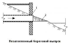
For flooded coastal outlets, coastal wells are installed with wastewater discharged below the water level in the reservoir. Unflooded coastal outlets, in accordance with the provisions of hydraulics, are considered as a connection of flows at different angles of confluence. Channel outlets are located at a certain distance from the shore.

Figure – Unflooded coastal outlet
1 – concrete wall; 2 – tray
The construction cost of onshore outlets is lower than the cost of channel outlets. However, at the outlet site, an insignificant initial mixing of flows is achieved, and, therefore, in practice they can only be used to discharge wastewater with a concentration of pollutants that do not affect the sanitary condition of the reservoir.
The choice of channel outlet design depends on:
sanitary requirements for diluting wastewater in a reservoir;
hydraulic flow structure;
channel morphology
geodetic marking of water levels in the coastal well and in the river.
The use of concentrated channel discharges is possible either by diluting the wastewater before release or if the dilution along the way to the design site is sufficient, i.e., the concentration of pollutants at the design site will correspond to the standard.
For the discharge of wastewater into rivers, it is always advisable to use dispersive outlets, and for the discharge of wastewater into stagnant reservoirs, the design of the outlet and its location in the reservoir should be determined by a technical and economic calculation.

Figure - Schemes of channel outlets
A – concentrated; B – scattering.
1 – coastal well; 2 – concrete head; 3 – heads with nozzles
The following titles exist:
cylindrical;
open scattering;
channel dispersive;
ejector nozzles.

Figure - Heads of scattering outlets
A – with a conical spreader; B – with outlet and nozzle; B – without nozzle.
1 – distribution pipeline; 2 – spreader; 3 – nozzle; 4 – gravel backfill
When designing sewer outlets at sea, one should take into account constant sea breezes on sea coasts, i.e. weak winds that blow from the sea towards land and drive floating impurities to the shore. Therefore, coastal-type marine sewage outlets are completely unacceptable, since they do not provide proper mixing of wastewater with sea water and do not make it possible to use the enormous self-purifying capacity of the sea.
It is recommended to equip marine-type outlets with a head with dispersing devices that ensure rapid and good dilution of the effluent with sea water. For better mixing of wastewater with sea water, the outlet at the end point of the outflow must be buried at least 10 m.
K category: Cleaning of drains
Discharge of wastewater into a reservoir
Treated wastewater during artificial treatment is discharged through a canal to the place where it is discharged into the reservoir. The diversion channel usually ends with a shore well, from which treated wastewater is discharged into the reservoir through an outlet. The more favorable the conditions for mixing the discharged wastewater with the waters of the reservoir, the better the self-purifying ability of the reservoir is used, the more contaminated the wastewater can be discharged into it.
Wastewater discharges are classified by type of reservoir (river, lake and sea), by location (shore, channel and deep) and by design (concentrated and diffuse).
Onshore concentrated outlets are designed in the form of open channels, fast currents, cantilever faults, and caps. In this case, a very slight dilution of the discharged wastewater with the water of the reservoir occurs, so the use of the self-purifying ability of the reservoirs is very low. Such outlets are used for the discharge of rainwater or lightly polluted wastewater. More often, channel dispersing outlets are installed to ensure the best mixing of wastewater with river water. Deep outlets are used when discharging wastewater into lakes, reservoirs, and seas.
The outlet is a perforated steel pipe with a metal casing with slots. The cage is filled with gravel or crushed stone. The area of the slotted holes in the lattice bottom of the cage is 40-50% of its area. The outlet of water in the form of vertical jets ensures effective mixing with the water of the reservoir.
Part 2
Treated wastewater is discharged through a canal to the point where it is discharged into the reservoir. The drainage channel usually ends with a coastal well, from which treated wastewater is discharged into the reservoir through the so-called outlet. The design of the outlet is essential for deciding the required degree of wastewater treatment. The more favorable the conditions for mixing the discharged water with the water of the reservoir, the more the self-purifying ability of the reservoir is used, the lower the required degree of wastewater treatment. The following discharge designs are distinguished: concentrated, through which water is discharged into the reservoir through only one hole; dispersive, in which water is discharged through a series of holes. In practical conditions, both outlets are used, but the dispersing outlet is more widespread, since it provides better mixing of wastewater with reservoir water.
Rice. 1. Dissipative outlet with tees and elbows

Rice. 2. General view of the dissipative release
The release should be brought to the middle of the river. Where the outlet is installed, the river bottom must be protected from erosion and siltation.
The choice of a place for discharging treated wastewater must be agreed upon with the sanitary inspection authorities, shipping departments and other organizations that are interested in maintaining the conditions of normal operation of the reservoir.
Currently, in most cases, the following designs of dispersive sewer outlets are used: outlets with tees and elbows (Fig. 1) and with tees (Fig. 2).
In Fig. Figure 2 shows a general view of the dissipative outlet of the Giprospetsneft structure with water distribution through tees.
Recently, Eng. A. X. Maksimov. (Leningrad) a simplified design of the dissipative outlet was proposed, providing good operating conditions. Water is released through holes in the pipe located at a certain distance from each other.
Eng. A. Kh. Maksimov also developed a theory for the hydraulic calculation of such a release, based on the fact that with the gradual distribution of water through the holes, the so-called movement of fluid with variable mass takes place.
- Release of wastewater into the reservoir
To discharge treated wastewater into reservoirs, two types of outlets are used: coastal and channel. Coastal outlets are divided into flooded and non-flooded. For flooded coastal outlets, coastal wells are installed with wastewater discharged below the water level in the reservoir. Unflooded coastal outlets (Fig. 4.145), according to
In connection with the provisions of hydraulics, they are considered as a connection of flows at different angles of fusion.
The construction cost of onshore outlets is lower than the cost of channel outlets. However, at the outlet site, an insignificant initial mixing of flows is achieved, and, therefore, in practice they can only be used to discharge wastewater with a concentration of pollutants that do not affect the sanitary condition of the reservoir.
Channel outlets are located at a certain distance from the shore. These outlets are divided into concentrated, scattering and ejector.
The choice of channel outlet design depends on the sanitary requirements for the dilution of wastewater in the reservoir, in addition, on the hydraulic structure of the flow, the morphology of the channel and on the geodetic markings of water levels in the coastal well and in the river.
The use of concentrated channel discharges is possible either by diluting the wastewater before release (when water is supplied from the reservoir by pumps to onshore contact reservoirs until the concentration of pollutants in the mixture is close in quantitative indicators to the standard), or if the dilution along the way to the design site is sufficient, i.e. the concentration of pollutants at the design site will correspond to the standard.
For the discharge of wastewater into rivers, it is always advisable to use dispersive outlets, and for the discharge of wastewater into stagnant reservoirs, the design of the outlet and its location in the reservoir should be determined by a technical and economic calculation.
If WATER DENSITY pst higher WATER DENSITY ditch in a reservoir, high-pressure distributors should be used to promote the distribution of wastewater to the entire depth. If the effluent density rst less than the density of water in a reservoir, low-pressure distributors with holes located at a minimum angle to the horizon (5-10°) should be used.
Based on laboratory research data from the VNII VODGEO, we can recommend the following outlets with heads: cylindrical; open scattering; channel dispersive with ejector nozzles.
A cylindrical type outlet head can be used to discharge wastewater into a river stream that provides an influx of sufficient river water to obtain the required initial dilution ratio.
Of interest is the design of the cylindrical outlet head, consisting of a cylindrical chamber with slots and a supply pipeline. The pipeline is connected to the cylindrical chamber at its end at an angle of ~45° (in plan), due to which a helical flow is formed in it, ensuring uniform discharge of waste liquid along the front of the structure.
The length of the cylindrical chamber is determined by the formula
bsr (N - £>)"
Where Q- water flow in the river, diluting wastewater in the initial section; рср, Н - average speed and depth of the river in the release zone; D- diameter of the cylindrical chamber;
N n n
K-factor equal to: at --- and at -<
The diameter of the cylindrical chamber is taken equal to D -
2 ... 3d, where
D- diameter of the supply pipe. Current speed in the inlet
the main pipe, at which the most favorable regime for the discharge of wastewater is observed, is 2-3 m/s. The maximum length of the cylindrical chamber in order to ensure uniform release along the length should not exceed 10D.
To wash the cylindrical chamber, its end is designed to be removable and bolted. In the riverbed, a cylindrical head can be installed using pile fastening.
|
Її-ж*
|

An open dissipative outlet head is a horizontally located conical pipe in which a cutout is made
Rice. 4.146. Diagram and design of the dissipative outlet
1 - pipe; 2 - release clip; 3 - gravel backfill;
4 - wall of the cage;
5 - lattice bottom of the cage; 6-sided outlet well: 7 - grate; 8 - onshore pipeline:9 - transverse walls of the cage; 10- Clip cover with holes; 11 - cracks in the pipe; 12 - supporting
Cross pipes
On the side surface (73 along the circumference), equipped with transverse guides. The waste stream, entering the head chamber, is cut by guides, resulting in a uniform discharge of waste along the front of the structure. The most favorable conditions are observed when the speed of the river flow is greater than the speed of outflow of waste liquid from the head. The flowing river flow in the outflow zone will create areas of low pressure, and an ejection effect occurs, which will intensify the dilution of wastewater.
The length of the head chamber can be determined by the average diameter DWITHR. The cone angle of the chamber is assumed to be 6-8°, its large diameter D6 = (l.5 ... 2)d, small diameter DM=(0.5 ... 1 )d, Where D- diameter of the supply pipe. The taper angle of the transition diffuser part is taken from the condition of flow continuity and is also 6-8°,
The calculation of dilution when using an open scattering head is carried out similarly to the calculation for a cylindrical head, if we take the average diameter of the chamber as the calculated one.
Thanks to the open design of the head, there is no need for special measures to clean it. In the riverbed, an open dispersive outlet head can be installed using a pile fastening.
In Fig. Figure 4.146 shows a diagram of the design of a dispersive filter jet outlet, which makes it possible to bring the purified water mixing point closer to the outlet itself. The outlet is a perforated steel pipe of constant cross-section with a metal clip welded to it along its entire length with slotted holes. The cage is filled with coarse gravel or crushed stone. The width of the collar, depending on the diameter of the pipe, is taken to be 150-400 mm, hi = 150 ... 200 mm, /i2 = 400 ... 600 mm. The area of the slotted holes in the lattice bottom of the cage should be 40-50% of its area. The release of purified water into the reservoir in the form of numerous vertical jets with a flow rate of 2-2.5 m/s ensures rapid and effective mixing with the water of the reservoir.
The channel dispersing head with ejector nozzles consists of a supply pipeline, its dispersing part, outlet pipes with nozzles and ejector chambers. The pipeline is laid in a trench with stone backfill, outlet pipes with nozzles are installed above the bottom surface and ejector chambers are installed. The ejector chambers can be mounted directly on the supply pipeline or independently, for example using piles.
According to LISI data, the maximum factor of the initial dilution corresponds to the following ratios of the dimensions of the ejector chamber:
OkonF=1>ZY G0RL; ^=4...5; 1<^ L<6, (4.304)
Where is A <онф - cross-sectional diameter of the confuser at the point of approach to it
A-eagle, - f-ropi - diameter and length of the cylindrical neck of the ejector. The cone angle of the confuser is assumed to be 30°, that of the diffuser is 7°.
The use of a channel dispersive outlet head with ejector nozzles can be recommended at low design flow velocities in the outlet zone (less than 0.1 m/s). Such conditions are typical, for example, in the upper reaches of reservoirs or in regulated sections of rivers.
When designing sewer outlets at sea, one should take into account constant sea breezes on sea coasts, i.e. weak winds that blow from the sea towards land and drive floating impurities to the shore. Therefore, coastal-type marine sewage outlets are completely unacceptable, since they do not provide proper mixing of wastewater with sea water and do not make it possible to use the enormous self-purifying capacity of the sea.
It is recommended to equip marine-type outlets with a head with dispersing devices that ensure rapid and good dilution of the effluent with sea water. For better mixing of wastewater with sea water, the outlet at the end point of the outflow must be buried at least 10 m.
Issues with ejecting heads are of significant interest. Such releases make it possible to reduce the concentration of pollutants by 1.5-3 times already at the time of wastewater discharge. This is achieved by increasing the rate of flow of water from the tips, as a result of which some amount of water surrounding the tip is drawn into the flow.
One of the main conditions for the uninterrupted operation of the outlet at sea is its high resistance to the effects of sea surf, which has great destructive power. The release fits normally to the storm resultant; the depth of its placement from the seabed mark should ensure the stability of the pipeline when the water level fluctuates during storms. Most often, the destruction of outlets occurs as a result of rupture of pipelines in the zone of breaking waves.
When laying pipelines at a depth of more than 10 m, there is no need to bury them in the ground, since the impact of waves here is insignificant.
A comparison of the technical and economic indicators of offshore release options from steel pipes laid in the underwater part and from cast iron pipes laid on pile supports shows that release from steel pipes is 15% cheaper. The protective coating for the inner surface of the walls of steel pipes is cement, while the outer surface is coated with bitumen, reinforced with fiberglass. A layer of concrete covering with a thickness of at least 100 mm is provided on top of the bitumen coating. Conical reinforced concrete diffusers are installed at the head of the outlet. The head is secured with a concrete block.
The head of the marine outlet must be sized to ensure its stability and reliable connection to the outlet pipeline.
Total informationWater outlet from reinforced concrete pipes DN500 mm; Hmax = 5.0 m; Qmax = 0.85 cu. m/s. General form. Cut 1-1. Plan
Water outlet from reinforced concrete pipes DN500 mm; Hmax = 8.0 m; Qmax = 1.00 cu. m/s. General form. Cut 1-1. Plan
Water outlet from reinforced concrete pipes DN500 mm; Hmax = 12.0 m; Qmax = 1.10 cubic meters m/s. General form. Cut 1-1. Plan
Water outlet from reinforced concrete pipes DN500 mm; Hmax = 5.0…12.0 m. General view. Cuts 2-2 - 5-5
Water outlet from reinforced concrete pipes DN600 mm; Hmax = 5.0 m; Qmax = 1.20 cu.m. m/s. General form. Cut 1-1. Plan
Water outlet from reinforced concrete pipes DN600 mm; Hmax = 8.0 m; Qmax = 1.40 cu. m/s. General form. Cut 1-1. Plan
Water outlet from reinforced concrete pipes DN600 mm; Hmax = 12.0 m; Qmax = 1.60 cu. m/s. General form. Cut 1-1. Plan
Water outlet from reinforced concrete pipes DN600 mm; Hmax = 5.0…12.0 m. General view. Cuts 2-2 - 5-5
Water outlet from steel pipes DN300 mm; Hmax = 5.0 m; Qmax = 0.25 cu. m/s. General form. Cut 1-1. Plan
Water outlet from steel pipes DN300 mm; Hmax = 8.0 m; Qmax = 0.30 cubic meters m/s. General form. Cut 1-1. Plan
Water outlet from steel pipes DN300 mm; Hmax = 12.0 m; Qmax = 0.35 cu. m/s. General form. Cut 1-1. Plan
Water outlet from steel pipes DN300 mm; Hmax = 5.0…12.0 m. General view. Cuts 2-2 - 3-3. Fragment 1
Water outlet from steel pipes DN400 mm; Hmax = 5.0 m; Qmax = 0.45 cu. m/s. General form. Cut 1-1. Plan
Water outlet from steel pipes DN400 mm; Hmax = 8.0 m; Qmax = 0.55 cu. m/s. General form. Cut 1-1. Plan
Water outlet from steel pipes DN400 mm; Hmax = 12.0 m; Qmax = 0.60 cu. m/s. General form. Cut 1-1. Plan
Water outlet from steel pipes DN400 mm; Hmax = 5.0…12.0 m. General view. Cuts 2-2 - 3-3. Fragment 1
Water outlet made of steel pipes DN600 mm; Hmax = 8.0 m; Qmax = 1.30 cu. m/s. General form. Cut 1-1. Plan
Water outlet made of steel pipes DN600 mm; Hmax = 12.0 m; Qmax = 1.50 cu. m/s. General form. Cut 1-1. Plan
Water outlet made of steel pipes DN600 mm; Hmax = 8.0…12.0 m. General view. Cuts 2-2 - 3-3
Water outlet from reinforced concrete pipes DN500 - 600 mm. Input heads ORm5, ORm6. General form
Water outlet from reinforced concrete pipes DN500 - 600 mm. Input heads ORm5, ORm6. Nodes
Water outlet from reinforced concrete pipes DN500 mm. Input head ORm5. Specification
Water outlet from reinforced concrete pipes DN600 mm. Input head ORm6. Specification
Water outlet from reinforced concrete pipes DN500 mm. Input head ORm5. Reinforcement scheme
Water outlet from reinforced concrete pipes DN600 mm. Input head ORm6. Reinforcement scheme
Water outlet from reinforced concrete pipes DN500 mm. Diaphragms. Pipeline foundations. General types
Water outlet from reinforced concrete pipes DN500 mm. Foundation for the OBm5 pipeline. Reinforcement scheme
Water outlet from reinforced concrete pipes DN500 mm. Diaphragm Dm5-1. Reinforcement scheme
Water outlet from reinforced concrete pipes DN500 mm. Diaphragm Dm5-2. Reinforcement scheme
Water outlet from reinforced concrete pipes DN600 mm. Diaphragms. Pipeline foundations. General types
Water outlet from reinforced concrete pipes DN600 mm. Foundation for the OBm6 pipeline. Reinforcement scheme
Water outlet from reinforced concrete pipes DN600 mm. Diaphragm Dm6-1. Reinforcement scheme
Water outlet from reinforced concrete pipes DN600 mm. Diaphragm Dm6-2. Reinforcement scheme
Water outlets from reinforced concrete pipes DN500 and 600 mm. Details of pipeline structures made of reinforced concrete pipes
Water outlets from reinforced concrete pipes DN500 and 600 mm. Output heads. General types
Water outlet from reinforced concrete pipes DN500 mm. Output head OVm5. Reinforcement scheme
Water outlet from reinforced concrete pipes DN600 mm. Output head OVm6. Reinforcement scheme
Water outlet from steel pipes DN300, 400 and 600 mm. Input heads OP3, OP4, OP6. General form
Water outlet from steel pipes DN300, 400 and 600 mm. Input heads OP3, OP4, OP6. Nodes
Water outlets from steel pipes DN300 and 400 mm. Input heads OP3 and OP4. Reinforcement scheme
Water outlet made of steel pipes DN600 mm. Input head OP6. Reinforcement scheme
Umbrella heads 03-1, 03-2. Assembly drawing
Umbrella heads 03-3, 03-4. Assembly drawing
Umbrella head 03-4. Specification
Umbrella head 03-5. Specification
Umbrella head 03-5. Assembly drawing
Umbrella head 03-6. Assembly drawing
Umbrella head 03-7. Specification
Umbrella head 03-8. Specification
Umbrella head 03-7. Assembly drawing
Umbrella head 03-8. Assembly drawing
Water outlets from steel pipes DN300 and 400 mm. Diaphragms. General types
Water outlets from steel pipes DN600 mm. Diaphragms. General types
Water outlets DN500 and 600 mm. Wells K-1, K-1A, K-2, K-2A. Specification
Water outlets DN500 and 600 mm. Wells K-1, K-1A, K-2, K-2A. General form. Plan. Nodes 2 - 4
Water outlets DN500 and 600 mm. Wells K-1, K-1A, K-2, K-2A. General form. Cut 1-1. Node 1
Water outlets DN500 and 600 mm. Wells K-1, K-1A, K-2, K-2A. General form. Cuts 2-2 - 6-6
Water outlets from steel pipes DN300 and 400 mm. Wells K-3, K-3A. Specification
Water outlets from steel pipes DN300 and 400 mm. Wells K-3, K-3A. General form. Cut 1-1. Plan
Water outlets from steel pipes DN300 and 400 mm. Wells K-3, K-3A. General form. Cuts 2-2 - 4-4. Nodes
Well K-4. General form
Water outlets from steel pipes DN600 mm. Output head. Specification
Water outlets from steel pipes DN600 mm. The exit head is supported by reinforced concrete piles. General form. Option 1
Water outlets from steel pipes DN600 mm. Outlet head with steel pipe support. General form. Option 2
Water outlets from steel pipes DN300 mm. Output head. Specification
Water outlets from steel pipes DN400 mm. Output head. Specification
Water outlets from steel pipes DN300 mm. Output head. General form
Water outlets from steel pipes DN400 mm. Output head. General form
Winter branch of the pipeline at Нз1 > 2.0 m. Specification
< 2,0 м. Спецификация
Winter branch of the pipeline at Нз1 =< 2,0 м
Winter branch of the pipeline at Нз1 > 2.0 m
Water outlets from reinforced concrete pipes DN500 and 600 mm. The end section of the water outlet with the outlet head OVUm5
Water outlets from reinforced concrete pipes DN500 and 600 mm. Output head OVUM5. Specification
Water outlets from reinforced concrete pipes DN500 mm. Output head OVUM5. General form
Water outlets from reinforced concrete pipes DN500 mm. Output head OVUM5. Reinforcement scheme. Cuts 1-1 - 3-3
Water outlets from reinforced concrete pipes DN500 mm. Output head OVUM5. Reinforcement scheme. Cuts 4-4 - 9-9
Water outlets from reinforced concrete pipes DN600 mm. Output head OVUM6. Specification
Water outlets from reinforced concrete pipes DN600 mm. Output head OVUM6. General form
Water outlets from reinforced concrete pipes DN600 mm. Output head OVUM6. Reinforcement scheme. Cuts 1-1 - 3-3
Water outlets from reinforced concrete pipes DN600 mm. Output head OVUM6. Reinforcement scheme. Cuts 4-4 - 9-9
Reinforcing mesh C1
Reinforcing mesh C2, C3
Reinforcing mesh C4
Reinforcing mesh C5
Reinforcing mesh C6
Reinforcing mesh C7
Reinforcing mesh S8, S8N
Reinforcing mesh S9, S9N
Reinforcing mesh C10, C11
Reinforcing mesh C12
Reinforcing mesh C13
Reinforcing mesh C14
Reinforcing mesh C15
Reinforcing mesh C16
Reinforcing mesh C17
Reinforcing mesh C18
Reinforcing mesh C19
Reinforcing mesh C20
Reinforcing mesh C21
Reinforcing mesh C22, C23
Reinforcing mesh C24
Reinforcing mesh C25
Reinforcing mesh C26
Reinforcing mesh C27
Reinforcing mesh C28
Reinforcing mesh C29
Reinforcing mesh C30
Reinforcing mesh C31
Reinforcing mesh C32
Reinforcing mesh C33
Reinforcing mesh C34, C35
Embedded product M1
Embedded product M2
Embedded product M3
Treated wastewater after disinfection is discharged through a closed pipeline or open channel to the point of discharge into the reservoir. The diversion channel usually ends in a coastal well, from which water is discharged directly into the reservoir through an outlet. [...]
The main task when installing an outlet is to achieve the most complete mixing of the outlet water with the water of the reservoir in order to obtain the greatest dilution of wastewater, which still contains a certain amount of contaminants.[...]
Depending on the shape and regime of the river section, when purified wastewater is discharged into it, a bank or channel outlet is arranged; the latter can be concentrated or dispersed. When discharging purified liquid into the sea or reservoir, coastal or deep-sea releases are arranged.[...]
Channel and deep-water outlets are made of steel, cast iron, reinforced concrete or concrete pipes protected from corrosion. The heads of all types of outlets are made primarily of precast reinforced concrete.[...]
When directly discharging wastewater near the shore, the release device is simpler (Fig. 4.151), but the degree of dilution is less than when releasing at some distance from the shore.[...]
Distributed release ensures better mixing of wastewater with reservoir water. Each issue ends with a title.[...]
It is advisable to take the current speed in the underwater part of the outlet as high as possible (not less than 0.7 m/sec) in order to protect it from silting.[...]
The head holes should be located at a sufficient height from the bottom (0.5-1 m) to avoid erosion of the bottom or drift of the head. The distance from the bottom surface of the ice to the holes must be at least 0.5-1 m.[...]
Depending on the depth of the reservoir, the thickness of the ice cover and the presence of navigation, the underbody part of the outlet is laid in a trench or directly along the bottom of the reservoir, secured with piles or with stone covering. Pipelines are laid in sections 50-100 m long from ice in winter, and from barges in summer. It is more convenient and cheaper to lay pipes from ice.[...]
When releasing wastewater into the sea, the outlet must be located outside the boundaries of the residential area and selected taking into account the direction of currents, wave formation, directions of prevailing winds, the presence of sea waves, etc. so that the removal of the discharged wastewater from the populated area by the sea is ensured with the current. The length of the outlet to the established depth of its mouth should be the smallest, the outlets are located at a depth of at least 1 m from the water level at low tide and at least 1 m from the sea bottom.