Installation of external water supply networks. Instructions for the installation of domestic water supply general information. Photo of the executed works
The design of the internal water supply system includes the following drawings:
Plans for floors and basement with lines, risers, pipelines, fittings, technological equipment, to which water should be supplied, a water measuring unit and other equipment;
Axonometric diagrams with pipelines, water and pipeline fittings and other equipment;
In May, an opening ceremony was held with the participation of the Federal President Johann Schneider-Amman. The project means studies close to touch, in order to live, experience and work in it. But, unlike other buildings, it is used not only for living and working, but also for testing and evaluating new integrated systems. During its use, the building will continue to change, change and be supplemented. Research and innovation units develop ideas from institutions and companies in market solutions.
Master plan (when laying the organization of external water supply networks and bushings);
Drawings and diagrams of pumping installations, tanks, water meters and other equipment;
Installation drawings of the system.
In the absence of installation drawings, they are developed.
The project is accompanied by an explanatory note with the calculation of the system, the characteristics of the equipment, as well as the specification of equipment and materials.
A two-storey penthouse, which will serve as a living and working space for guests, will highlight the opportunities offered by lightweight structures and new engineering solutions. The first module will be completed at the end of this year and will soon be available.
This corresponds to the vision of the doctor. The research community will work with industry to develop new ways to increase the overall energy efficiency of buildings. This platform can be connected with various renewable energy sources and various local storage systems.
Installation of the water pipe is carried out in accordance with the project for the production of works, a schedule of works on the site and performed simultaneously with other sanitation systems. In winter, the installation of a water pipe usually begins after the start of the heating system.
Installation of a waterpipe lead in such sequence. Pipes are put through, quarterly networks, after which they are tested and made a side-by-side in the external water supply networks. Then, the water supply network of the building and equipment (water meters, pumps, tanks) is installed. After the end of the installation, the pipelines are washed, the operation of the water pipe is checked.
Are the individual modules already assigned to specific teams? The focus of her current research is on how high-resolution numerical analysis affects the design of sustainable buildings. What aspects affect your research? In fact, these are changing energy rules for the design of buildings. To achieve this, new concepts are required for the design and construction of clean buildings with zero energy on a large scale. For these concepts, modern building simulations are also used.
Before starting the installation, the building must be ready for construction. Installation of pumps and water heaters is the same as in heating systems.
When installing the water pipe, use the tool kit shown in the section "Installing the heating devices".
In the absence of heating, the rooms are insulated, cleaned of snow and debris. Connection of inputs to external networks, testing and commissioning of water pipes are made only after starting the heating system and warming up the premises. Polyethylene pipes are mounted at a temperature of at least -10 ° C. When installing plastic pipes in a heated room they are kept indoors for two to three hours.
In addition, modern building technologies, such as numerical fluid mechanics, are becoming increasingly important for modern building design. Arno Schluter on new concepts and modeling procedures for planning low-energy buildings.
How does the external climate affect effective building systems, architecture and urban planning? The external climate plays an important role in the planning of buildings. For this construction project, the team developed a special concept of energy, which not only reduces the spatial consumption of the building, but also lowers the operating costs for cooling and dehumidification.
Installation of quarter networks and inputs
Quarter networks of cold water supply and inputs are laid in the ground at a depth of 0.5 m below the depth of freezing. To reduce construction costs, the water pipe is laid in one trench with heat networks, using cellars and technical underground buildings for transit pipelines. In large microdistricts with a significant amount of communications for this purpose, pass-through or non-flow channels are used.
Installation of water and sewage
In this case, the external climate was the dominant factor for planning. The quality of indoor air, which depends mainly on room temperature and ventilation, affects the health of children and the ability to learn. Children suffer more from a bad internal climate than adults, since their respiratory system is not yet fully developed. In terms of body weight, children also breathe more air than adults.
What are your goals or expectations regarding rules, technologies, procedures or a common understanding of such projects? Innovative construction in an actual environment usually requires a lot of planning effort. These projects provide results of studies of international importance that can be quickly translated into improved energy concepts for buildings. It consists of mobile modules, which, on the one hand, take on the production of energy and shading, and on the other - control the transparency of the facade.
The water mains should be laid at a distance (horizontally) not less than 1.5 m from the sewer pipes with a diameter of up to 200 mm and 3 m - for pipes of larger diameter. At the intersection of water and sewage pipelines, the distance in the light should be not less than 0.4 m, when crossing with other pipelines - not less than 0.2 m.
Networks are laid in the following order:
Elements of the module can rotate to respond to external changes and internal requirements at will. Such innovative systems will play a central role in achieving ambitious energy efficiency goals in Switzerland and Europe for buildings. More detailed information can be found in our recently published article "Boundaries of Architectural Research".
Will the results obtained with the first module receive the next stage of construction? To improve the performance of the building, internal sensors and a modern server will monitor power systems and testing algorithms. This will be very interesting for research, since the modeling of future construction projects will be calibrated based on recorded measurement results. Thanks to the integrated hydraulic line system, the roof can also be used as a thermal active building system.
Mark the track and tear off the trench;
Then the joints are sealed or welded;
Install the stops;
Rinse and test the pipeline;
They build wells, fall asleep a pipeline.
The breakdown of the route begins with the transfer to the terrain of characteristic points - well centers, turning angles, intersections with existing communications and structures that are tied to existing buildings and structures. These points are fixed with pegs, between which a string is drawn, denoting the axis of the pipeline.
The approach to accounting for not only the useful energy, but also the gray energy determines the whole project. Do you think the biggest achievement of this project is if you can choose one achievement? It was developed in a relatively short period of time by a team of researchers and consultants.
Thanks to this close cooperation in the field of science and practice, we were able to develop solutions that would show the industry new ways to achieve sustainability. If you travel by train or car between Montreux and La Villeneuve, you can enjoy a beautiful view.
Trench for digging pipelines and pits under the wells are developed by digging machines. The width of the bottom of the trench is 0.5 + 0.6 m larger than the diameter of the pipe. The trench is torn to the depth not more than the design one. At the locations of the joints of the pipelines, pits are dug out for the convenience of sealing the socket joints or welding. The walls of the trench must have natural slopes or inventory fasteners. Pipes are neatly stacked in a trench: they are not to be dropped or rolled down the slope of the trench.
Installation of quarter networks and inputs
This doubling of capacity is achieved with relatively little intervention, as the new facility uses the existing Khongrin reservoir at an altitude of 800 m as the upper reservoir and Lake Geneva as an underwater basin. When using these two storage tanks for the operation of both systems, there is sufficient water. The new system continues to use existing 8 km supply routes to the pressure line.
What are the special problems of this power plant and the differences with other power plants? The pressure head 800 m is controlled by two 5-stage pumps. In addition, the new plant will be connected to the water pipes under the pressure of the existing plant. During the outbreak of the new cave and communication with the existing system, operational restrictions should have been minimized.
Trumpet pipes are usually laid, starting with the lowest mark, with flaps against the slope. At each turn, there is a stop that senses the force of the water pressure, and also prevents the pipeline from shifting under the influence of pressure and a breach of the tightness of the butt joint.
Joints of cast-iron and asbestos-cement pipes are sealed with an asbestos-cement mixture, steel pipes are welded and coated with reinforced anticorrosive insulation. Pipelines of hot water pipe are covered with thermal insulation.
Photo of the executed works
What are the requirements for engineers in such a project? Specialists are required who, in addition to their specialized knowledge, also understand the system in a general concept and cover numerous interfaces. This means that, in addition to the experience of each student, communication and close coordination and cooperation among all the parties involved are particularly important.
And what is the purpose of the new system? Because the increase in the supply of electricity from wind and solar power stations in our electrical network is irregular and fluctuates. Thus, a power plant with a pumping storage provides valuable control and peak energy to compensate for fluctuations and provide power flexibly and quickly when end users demand it. Can the plant continue to be used in today's electricity market? Well, the decision to build this plant, as well as the construction of further plants in Switzerland, which must be completed, was made up to historically low prices for electricity.
When laying pipes in channels connecting the technical underground and the basement of several houses, the pipes are mounted on supports. After testing the pipelines, the channels in the collectors are covered with a slab of overlapping and covered with earth. In the passageways, collectors pipes are fed through the installation openings in the ceiling or through technical underground. The water supply, as a rule, is placed under all communications at the bottom of the collector.
However, the installation is necessary for the reasons mentioned above, and will be beneficial throughout its life. Recall: the first large-scale hydroelectric power plants in Switzerland were created more than a hundred years ago. Although they have long been depreciated, they are still in operation due to our high engineering and construction skills. In the future, hydropower will and will remain the most important source of renewable energy for Switzerland.
Proven and sustainable: small hydroelectric power plants
56% of the energy produced in Switzerland is generated by water energy. Recently, a study was published that, at first glance, did not make Switzerland very positive with respect to renewable energy sources. Only solar energy and wind energy were considered. Not taken into account, and therefore not mentioned further, became hydropower, which is so important for Switzerland.
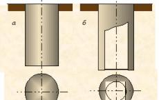
Input pipelines ( fig.1, a) are laid in the ground just like quarterly networks. The distance between the inlet and outlet of the sewer should be the same as for the pipelines of the quarterly network. The pitch of the input is provided in the direction of the external network. In the place where the input is connected to the external network, a valve is installed in the well 2. The input is connected to the tee or cross of the external network.
Construction of an autonomous system
56% of the energy produced in Switzerland is generated by hydropower. This remains at the moment the most important and most consistent source of energy. The study also did not take into account that the geographical position is unlikely to allow it to equal the level of wind power, as in Germany; did not even mention the protection of the environment and nature protection, to which wind power will greatly influence.
Connection to the central engineering networks
Although most hydropower is produced by large factories, small-scale hydropower plants play an important role in nationwide and reliable supply. The fact that the further expansion of small hydropower plants is assessed as relatively low is due not only to careful use of the environment and nature, but also to the fact that Switzerland began to expand it with renewable energy sources over a hundred years ago, when this term did not even exist.
Fig.1. Input device (a) in dry (b) and wet (in) ground
1 - connecting piece;
2 - gate valve;
3 - pipeline;
4 - wall of the building;
5 - clay;
6 - cement strainer;
7 - strand;
8 - bolt;
9 - flange.
Entering a water pipe passing through the wall 4 basement, lay with a gap of at least 200 mm from the building (wall) of the building. In dry soils ( fig.1, b) this gap is filled with resin strand 7 and mint clay 5 and on both sides the walls are covered with a cement screed 6. In wet soils ( fig.1, c) apply water and gas tight seals. Beyond the wall of the building 4 install a valve behind which a water meter assembly is mounted.
We want to briefly highlight these precious stones of renewable energy. What makes a small hydropower plant different from a large power plant? In addition to lower installed capacity and therefore less predictable annual production, the efficiency is about 3-4% lower than for large power plants. The functionality is almost the same.
What technologies are used in small hydroelectric plants? Small hydropower plants use known and proven technologies, such as the Pelton turbine, which is used at a drop height of at least 30 m and small amounts of water or a Kaplan turbine, which can use smaller drop heights from 2 to 20 m with a large amount of water.
When two or more entrances are inserted into a building, they are united and a bolt is installed between them. A non-return valve is installed at the inlet when there are water tanks in the building or several piping connected by pipelines.
Pipe insertion 9 in the existing water supply system is made by means of a device ( fig. 2). To do this, first weld the adapter 10 to the existing pipeline 11 external network. On the branch pipe install the device for the tie-in and fix it with bolts to the flange of the branch pipe. When the flywheel is rotating, the shaft 6 receives forward motion, resulting in a drill bit 1, and then a milling cutter 2 , attached to the shaft, drill a hole in the pipeline. The water fills the internal cavities of the branch pipe and the fixtures. The drill and milling cutter are taken out of the hole by lifting the flywheel with the stem, and the hole in the adapter 10 it is closed by the valve 3, which is raised by pulling the rope 4 through an omentum 5 . The water pressure tightens the valve 3 to the hole in the adapter. After that, the device is removed and the valve is pulled with a screw to the plug.
What resources can I use? Flows, rivers, water sources, water supply networks, sewerage systems, water and sewage systems, pressure relief in industry and process, as well as residual water from large power plants can be used as hydraulic power sources.
Independence from the weather Regardless of the time of day Low operating costs. Of course, besides the positive aspects, there are also some things in hydropower. Water should be protected in terms of various factors, such as residual water flow, fish migration, silting, water fluctuations, etc. economically high investment costs are in the room. The possibility-risk assessment should be specified in each specific case.

Fig.2. Pipe insertion tool
1 - drill bit;
2 - milling cutter;
3 - valve;
4 - cable;
5 - stuffing box;
6 - shaft;
7 - feeding device;
8 - the body;
9, 11 - pipelines;
10 - branch pipe.
When the diameter of the input is less than 1/3 of the diameter of the pipe of the external network, it can be connected by means of couplers.
If there are no specific instructions on the order of work on the laying of pipelines in the production design, the installation is carried out in the following order: arrange the bottoms of the wells and chambers until the pipes and their installation are lowered into the trench; lay pipes; mount the shaped parts in the places of installation of wells and chambers; seal butt joints; erect walls of wells and chambers.
Pipes connected on the funnels are laid from the bottom upwards (against the flow of the transported medium) by the funnels forward in the course of the installation.
Prior to the installation of pipelines, it is necessary to arrange an end stop at the beginning of the section, used for both installation and testing of the pipeline.
Butt joints of cast iron socket pipes are sealed with rubber cuffs (for pipes up to 300 mm in diameter), rubber round rings (for pipes with a diameter of more than 300 mm), or joints with a hemp resin or bituminous strand, followed by locking from an asbestos cement mixture or cement mortar. Rubber seals are installed at a temperature of at least -20 ° C.
Joints of reinforced concrete spigots and asbestos-cement pipes, with their smooth ends, when sealed on couplings, are sealed with rubber rings.
Polyethylene pipes are connected by welding or sockets with rubber sealing rings.
Steel pipes are mainly welded together. Steel pipes are connected with water valves on flanges, rubber gaskets or tarred cardboard are installed between the flanges.
Pipes before laying in a trench inspect. It is not allowed to lay pipes: cast iron with cracks and spalling of the ends; asbestos cement with cracks, stratifications of material or splits on the ends, as well as asbestos cement joints with damaged collars, reinforced concrete with cracks on the outer and inner surfaces, delamination of the protective layer of concrete, with longitudinal risks, shells and concrete splits on the bushing end of the pipe and on the inner surface of the bell in places of installation of a rubber sealing ring; plastic (polyethylene) with cracks, cuts, risks and other mechanical damages more than 5% of the pipe wall thickness. Pipes, the dimensions of which have deviations exceeding those permitted by GOSTs, can not be mounted.
Before laying the pipes in a trench, the foundation marks are checked by leveling. The deviation of marking of the pipe tray in front of the well from the design should not exceed ± 5 mm. Pipes should be laid in a trench, observing the specified design position in the horizontal and vertical planes.
Butt joints must be carried out mainly by means of mounting tensioning devices.
Installation of pipelines from reinforced concrete socket pipes with sealing of butt joints with rubber rings. After the preparation of trenches for laying pipes, digging pits, dewatering devices from the trench, setting up a level of two sighters on the edge of the trench (at a distance of 35-40 m from each other), removing the pipeline axis with the installation of poles in the wells and trench, verification of the correspondence of reinforced concrete pipes and materials for sealing joints of GOSTs and specifications, cleaning pipes from contamination and ingress of concrete and providing workers with tools to lay reinforced concrete pipes in a trench.
Pipelayer on the template marks on the smooth end of the stacked pipe the depth of its sealing in the socket previously laid. The operator installs the faucet opposite the stacked pipe so that his arrow is above the center of gravity of the pipe, and lowers the semiautomatic grip on the pipe. Then the pipelayer unhooks the hook holding the tongs in the open position, and instructs the machinist to lift the pipe.
The pipe is raised by 20-30 cm. Then the crane operator, having ascertained the reliability of the slinging, continues lifting the pipe to a height of 1 m and turning the boom of the crane guides the pipe into the trench. Pipelayers keep the pipe from turning.
Having suspended the descent of the pipe at a height of 0.5 m from the base of the trench, the pipelayers put a rubber, pre-cleaned O-ring on its smooth end so that it is tightly placed along the contour in the socket. The pipe is lowered to the position necessary to bring it into the socket, after which the pipe layers plant the smooth end of the pipe into the socket previously laid.
To align the pipe vertically, the pipe-laying unit installs the chute on the stack of the pipe to be laid, and the other pipe-laying machine checks the line of sight while being at the front fixed sighting vane. The crane operator, at the command of the pipe-laying operator, raises or lowers the pipe, the pipelayers at the same time punch or cut the ground under the pipe. When the alignment is completed vertically, the grip is removed.
To align the pipes in the plan, they set up the vests and, with the help of scraps, shifting the end of the laid pipe to the desired side, making sure the pipe position is correct in the plan.
Reinforced concrete spigot tubes are joined by means of various mechanisms and devices.
Pipe connection using a tensioning device installed inside the pipe. In this case, a screw spacer is installed inside the previously laid pipe with an inclination towards the socket. Further, a wooden beam and a beam of a tensioning device are placed in the socket of the laid pipe. The rods are attached to the tension screws and fixed to the screw spacer. Evenly pulling the traction with the nuts of the tension screws, insert the smooth end of the laid pipe into the socket previously installed.
During installation, check the uniformity of the rolling of the rubber ring; If necessary, the ring and the smooth end of the pipe are powdered with cement.
After the end of the joints, the tensioning device is removed, while the pipe, under the action of internal forces that have arisen in the sealing ring, moves slightly away from the stop of the socket, forming a gap.
Pipelayers pile the pipe with soil to the height of its diameter, and then compact the soil with hand tamper.
Pipe joining with screw type tensioner with hinged whirlpool. The hinge clamp is fixed to the socket of the second or third laid pipe. The spigot end of the pipe to be laid is fitted with a support spigot with a tensioning screw and a working (movable) spider. One end of the ropes is fixed on the yoke, the second is put on the adjusting screws. By rotating the tension screw, the working cross is driven, the ropes are smoothly tensioned, and the smooth end of the laid pipe is inserted into the socket previously laid.
Connecting the pipes with a winch. After installing the thrust beam and fixing the blocks, place the winch. The pulling rope of the winch with one end with a loop is passed through the hook of the half-hammer, then it is stretched to the other side of the pipe, passed through the second hook of the half-hammer, then through the blocks lead to the winch and put a loop on its hook. With the help of the winch lever, the rope stretches, moving the stacked pipe and the smooth end of the pipe is inserted into the socket previously laid.
Pipe connection using a gear winch. The winch is installed and fixed on a previously laid pipe. The winch rope is fixed on the laying pipe. Turning the handle of the drum, the rope stretches, while the stacked pipe moves in the direction previously laid to the end position. After removing the rope and capturing the next stacked pipe, a second pipe is mounted. Thus, without removing the winch, you can connect several pipes.
Pipe connection with rack and jack and concrete stop. Before the funnel of the laid pipe, a temporary concrete stop is set using a crane. The bars are installed on the end of the socket of the laid pipe. By force of the jack, the stacked pipe moves to the side of the docked pipes laid to the required position.
Pipe connection with a bulldozer. In the socket of the stacked pipe, place the wooden beam so that it protrudes slightly beyond the end of the socket. The bulldozer is equipped with a special wooden beam, the pressure of which on the wooden beam, installed in the socket of the laid pipe, moves the pipe towards the previously stacked pipes to the required position.
Mounting of cast iron socket pipes with sealing of butt joints with rubber seals. To ensure the tightness of the butt joint, a rubber seal - a cuff or a circular ring - is inserted into the socket. The airtightness is created by radial compression of the rubber seal in the socket socket by the inner surface of the socket and the outer surface of the smooth end of the pipe. The seal is held in the socket socket by a screw locking sleeve, locking tooth or flange. With a flange joint with nakidnymi bolts tightness of the joint is achieved by tightening the bolts, and there is an axial compression of the rubber seal in the spherical groove of the socket.
When installing pipelines from cast iron socket pipeswith installation in the bell mouth as a rubber ring seal, the installation sequence is the same as for the cuff installation. The difference is that before inserting the smooth end of the pipe to be mounted, a sealing rubber ring is placed in the socket of the pipe previously laid in the trench on the smooth end of the pipe to be mounted.
Having verified the position of the pipe to be mounted in vertical measurement and in plan, the pipes are joined by means of a mounting device. Folding cap is put on the previously laid pipe at the place of its transition into the bell. Tie-bars are attached with the first channel stop, the second channel stop should lie on the end of the stacked pipe. A radially thrust bearing is located between the two channel stops. Rotating the handle with an end bolt with a toothed pin attached to the end, the smooth rings of the pipe to be mounted are fed into the socket of the second channel stopper, which is pushed apart from the spacing.
After the pipes are docked, the tensioning device is removed, the piping is pummeled, poured into the soil and compacted with ramers from both sides to a height equal to the diameter, thereby securing the pipeline to the design position.
You may also be interested in: